


- 24 -
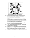
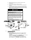
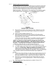
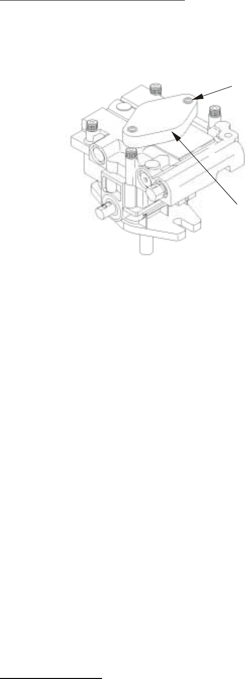
CHARGE PUMP CA
P
LOOSEN 1-1/2
TURNS ONLY
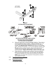
5.1.11 Hydraulic system air purge procedure.
Air must be purged from the hydraulic system when any hydraulic components,
including oil filter, are removed or any of the hydraulic lines are disconnected.
The critical area for purging air from the hydraulic system is between the oil
reservoir and each charge pump located on the top of each variable
displacement pump. (See Figure 6). Air in other parts of the hydraulic system
will be purged through normal operation once the charge pump is “primed”.
FIGURE 6
CHARGE PUMP LOCATION
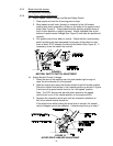
a) Stop engine and wait for all moving parts to stop. Raise the rear of the
machine up onto jack stands high enough to raise the drive wheels off
the ground.
b) Check oil level as stated in Section 5.1.9.
c) Start engine and move throttle control ahead to full throttle position.
Move the speed control lever to the middle speed position and place the
drive levers in the “drive” position.
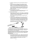
If either drive wheel does not rotate, it is possible to assist the purging of
the charge pump by carefully rotating the tire in the forward position.
NOTE: It is necessary to lightly touch the charge pump cap with your
hand to check the pump temperature. If the cap is too hot to touch, turn
off engine. The pumps may be damaged if the pump becomes too hot.
If either drive wheel still does not rotate continue with step (d).
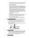
d) Thoroughly clean the area around each of the charge pump housings.
e) To “prime” charge pump, loosen two hex socket head capscrews (shown in
Figure 6) 1-1/2 turns only. Make sure engine is not running. Lift the
charge pump housing upward and wait for a steady flow of oil to flow out
from under the housing. Retighten the capscrews. Do this for both pumps.
Note: Hydraulic reservoir can be pressurized up to 5 psi to speed this
process.
f) If either drive wheel still does not rotate, stop and repeat steps (d) and (e)
above for the respective pump. If wheels rotate slowly, the system may
prime after additional running. Check oil level as stated in Section 5.1.9.
g) Allow unit to run several minutes after the charge pumps are “primed”
with drive system in the full speed position. Check oil level as stated in
Section 5.1.9.
h) Check hydro drive linkage adjustment as stated in Section 5.2.5.
5.1.12 Check tire pressures.
Service Interval: 40 hrs.