


- 13 -
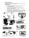
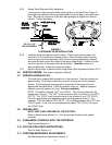
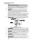
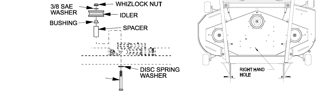
3.5.5 Mower Deck Stationary Idler Installation:
Locate the two holes along the back center section of the deck (See Figure 2)
and install the stationary idler and related parts (from bolt bag) in the right hand
hole. Be sure the coned end of the disc spring washer is against the head of
the bolt. Tighten hardware.
FIGURE 2
STATIONARY IDLER INSTALLATION
3.5.6 Install the deck drive belt around the clutch. Refer to belt routing decal. Be
sure belt is in the clutch drive sheave groove. Place the other end of the belt
into the V-groove of the stationary idler, move the spring loaded idler outward
and route the belt around the inside of the spring loaded idler. Position the belt
into the V-groove of the mower deck drive sheave. Carefully release the
spring loaded idler. Install the center belt shield.
3.5.7 Adjust cutting height of deck and anti-scalp rollers (See Adjustment Section 5.2.1).
3.6 SERVICE ENGINE: See Engine Operator's Manual.
3.7 SERVICE HYDRAULIC OIL
The machine is shipped with hydraulic oil in the reservoir. Run the machine for
approximately 15 minutes to allow any extra air to purge out of the hydraulic
system. Check hydraulic reservoir and if necessary fill the reservoir to the
appropriate level with Mobil 1 15W-50 synthetic motor oil. Replace hydraulic
reservoir cap and tighten until snug. Do not overtighten.
NOTE: The baffle is labeled “HOT” and “COLD”. The oil level varies with the
temperature of the oil. The “HOT” level shows the level of oil when it is at 225°F
(107°C). The “COLD” level shows the level of the oil when it is at 75°F (24°C).
Fill to the appropriate level depending upon the temperature of the oil. For
example: If the oil is about 150°F (65°C). Fill to halfway between the “HOT” and
“COLD” levels. If the oil is at room temperature (about 75°F (24°C)), fill only to
the “COLD” level.
3.8 GREASE UNIT:
NOTE: UNIT IS NOT GREASED AT THE FACTORY.
Refer to Maintenance Section 5.1.14 for grease zerk locations and grease
amounts.
3.9 FAMILIARIZE YOURSELF WITH THE CONTROLS.
See Controls Section 4.1.
3.10 FOLLOW PRE-START INSTRUCTIONS.
See Pre-Start Section 4.2.
3.11 PERFORM NECESSARY ADJUSTMENTS.
See Maintenance and Adjustment Section 5.
3/8-16 x 4 1/2
HEX CAPSCREW