


Maintenance
Adjustments
Note: Disengage PTO, shut off engine, wait for
all moving parts to stop, engage parking brake, and
remove key before servicing, cleaning, or making any
adjustments to the unit.
Deck Leveling
1. Position mower on a at surface.
2. Stop engine, wait for all moving parts to stop, and
remove key. Engage parking brake.
3. Check tire pressure in drive tires. Proper ination
pressure for tires is 13 psi (90 kPa). Adjust if
necessary. Semi-pneumatic caster tires Do Not
need to be inated.
4. Set anti-scalp rollers to top holes (if installed) or
remove them completely for this adjustment.
5. Lower the deck to the 1 1/2 inch (3.8 cm) height
position. Place two 1 1/8 inch (2.9 cm) thick
blocks under the rear edge of the cutting deck
skirt; one on each side of the cutting deck.
6. Place a 1 inch (2.5 cm) block under the center
front edge, but not under the anti-scalp roller
brackets.
7. Loosen the four bottom chain bolts in slots until
the deck is supported by the blocks. Take the
slack out of the chains and retighten the hardware.
8. Recheck that blocks t just snugly under the
deck skirt and that the tension on all the chains
is approximately equal. Make sure all chain
attachment bolts are tight.
9. Reposition anti-scalp rollers (if installed) and
tighten securely.
Note: When above adjustments have been made,
the front of the deck will be slightly lower than the
rear of the deck.
Pump Drive Belt Tension
Self-tensioning - No adjustment necessary.
Deck Drive Belt Tension
Self-tensioning – No adjustment necessary.
Electric Clutch Adjustment
No adjustment necessary.
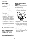
Motion Control Linkage
Adjustment
Note: There are two lever height options available.
Place the levers in the top two holes to increase
height of the levers, or in the bottom two holes to
decrease the height of the levers.
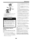
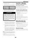
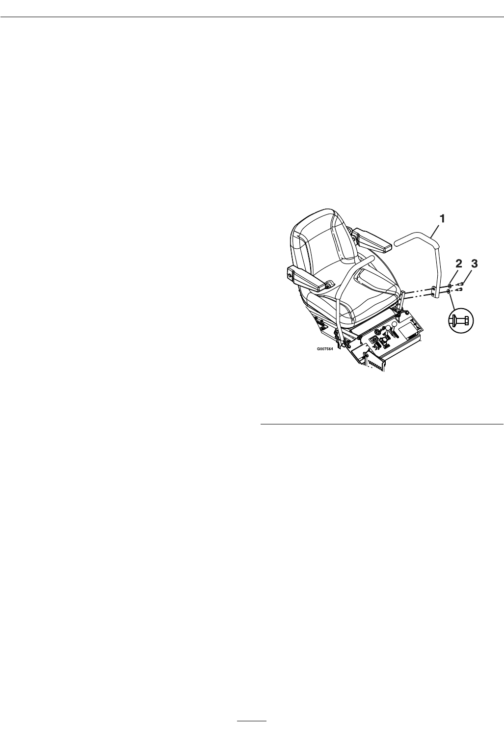
1. Align the levers front/rear position. With the
levers in the neutral position, loosen the hardware
and adjust the levers sliding and/or tilting the
lever(s) forward or backward until properly
aligned and tighten hardware (Figure 11).
Figure 11
1. Motion control levers
3. 3/8-16 x 1 inch screw
2. Spring disc washer
2. If the ends of the levers hit against each other,
while in the drive position (levers rotated in as
far as possible), make adjustments by moving the
levers outwards to the neutral lock position and
carefully bending them outward. Move them back
to the drive position and check for clearance.
Repeat if necessary.
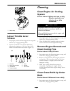
3. If the machine turns right or left when handles are
pushed forward together, adjust the stop on the
side opposite the direction of turn (see Figure 12).
Move the stop back until the unit drives straight.
Readjust handles if necessary.
28