


Setup
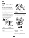
9. Place the cable into the cable bracket notch and
secure with the two nuts. Make sure the nuts are
centered on the bracket.
10. Wrap the cable hanger strap over the cross shaft
and feed the loose end of the cable through the
strap holes as shown in Figure 5. Route the cable
around the back side of the cross shaft. Install the
other cable hanger strap on the right side of the
cross shaft. Set the cable aside.
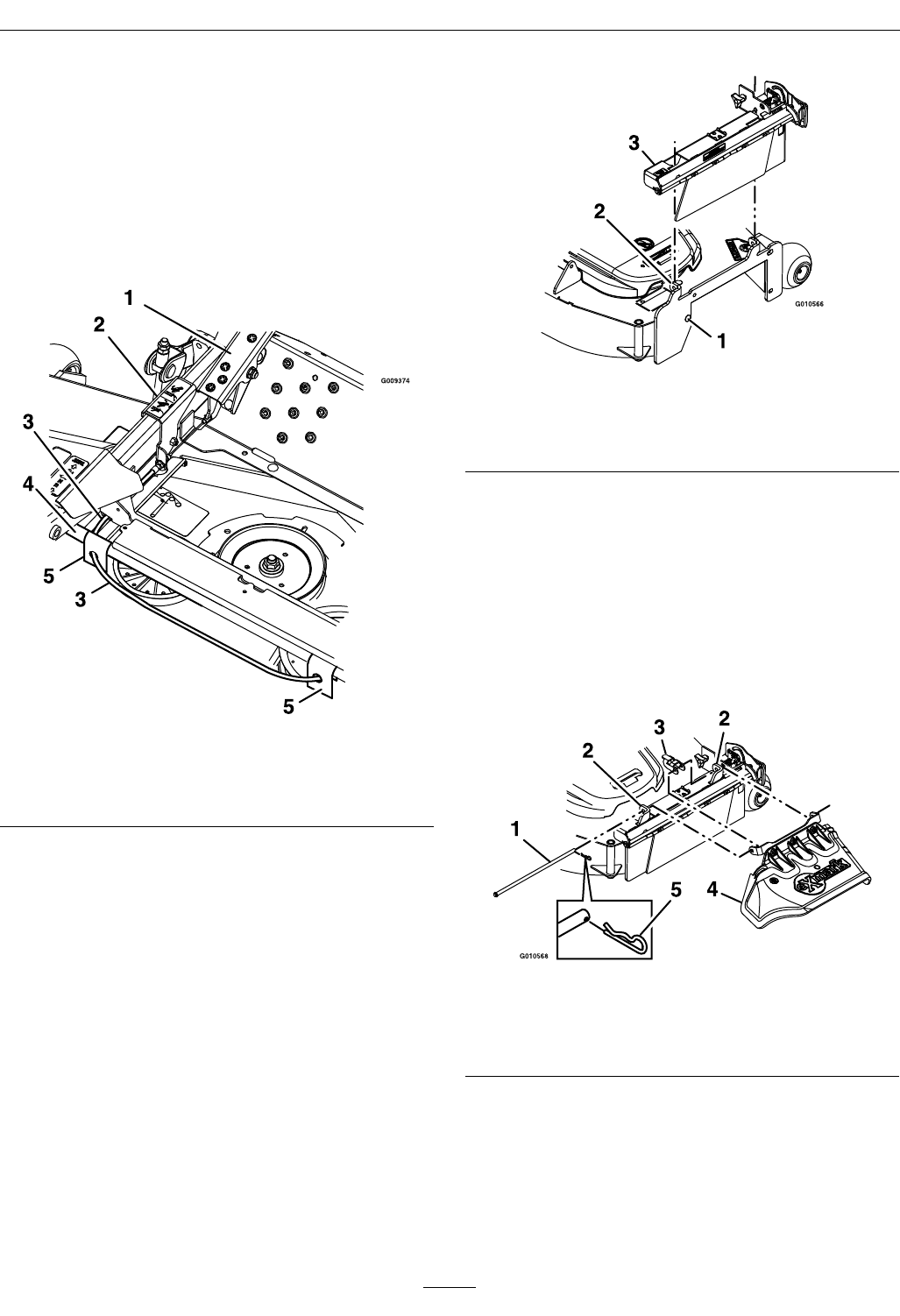
Figure 5
1. Foot pedal
4. Cross shaft
2. Cable bracket 5. Cable hanger strap
3. Cable
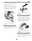
11. Install the gate linkage assembly onto the deck as
shown in Figure 6. Make sure the discharge bafe
bolt head is positioned to the outside of the deck.
Turn the bolt around if necessary.
Figure 6
1. Discharge bafe bolt
head
3. Gate linkage assembly
2. Deck tab
12. Insert the chute pivot rod through the rst tab
on the deck, gate linkage assembly, and discharge
deector (see Figure 7). Install the link pivot
bracket onto the link pivot channel, located on
the gate linkage assembly. Route the chute pivot
rod through the link pivot bracket, the tabs on
the deck, gate linkage assembly, and discharge
deector and install the hairpin. Orient the
hairpin as shown in Figure 7.
Figure 7
1. Chute pivot rod 4. Discharge deector
2. Deck tab 5. Hairpin
3. Link pivot bracket
13. Push down the front of the foot pedal and place
the link pivot bracket in the unlocked position
(Figure 8), attach the cable end onto the gate lift
link. Orient the hairpin as shown in Figure 8 and
install into the gate lift link.
9