


- 23 -
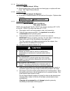
5.1.8 Check hydraulic oil level:
Service Interval: 40 hr.
a) Stop engine and wait for all moving parts to stop.
b) Tilt hopper up.
c) Clean area around hydraulic reservoir cap and remove cap. Oil level should
be to the top of the baffle inside the tank. If not, add oil. Use only Mobil 1
15W-50 synthetic motor oil. Replace hydraulic reservoir cap and tighten
until snug. Do not overtighten.
NOTE: The baffle is labeled “HOT” and “COLD”. The oil level varies with
the temperature of the oil. The “HOT” level shows the level of oil when it is
at 225°F (107°C). The “COLD” level shows the level of the oil when it is at
75°F (24°C). Fill to the appropriate level depending upon the temperature
of the oil. For example: If the oil is about 150° F (65°C), fill to halfway
between the “HOT” and “COLD” levels. If the oil is at room temperature
(about 75° F (24°C)), fill only to the “COLD” level.
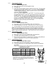
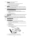
5.1.9 Check tire pressures
:
Service Interval: 40 hrs.
a) Stop engine, wait for all moving parts to stop, and remove key.
b) Check tire pressure in drive tires. Inflate drive tires to 15 psi (103 kPa).
c) The rear caster tire is semi-pneumatic and does not need to be inflated.
NOTE: Do not add any type of tire liner or foam fill material to the tires.
Excessive loads created by foam filled tires may cause failures to the hydro drive
system, frame, and other components. Foam filling tires will void the warranty.
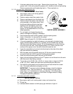
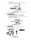
5.1.10 Check condition of belts
:
Service Interval: 40 hrs.
a) Stop engine, wait for all moving parts to stop, and remove key.
b) Tilt hopper up and check pump and PTO drive belts.
c) Belts are spring tensioned and no adjustment is necessary unless belts are
replaced. See section 5.2.2 and 5.2.3 for belt replacement.
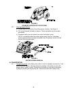
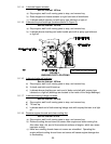
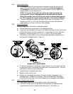
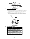
5.1.11 Lubricate grease fittings
:
Service Interval: Refer to chart.
a) Stop engine, wait for all moving parts to stop, and remove key.
b) Lubricate fittings with one to two pumps of NGLI grade #2 multi-purpose
gun grease.
Refer to the following chart for fitting locations and lubrication schedule.
LUBRICATION CHART
FITTING
LOCATIONS
INITIAL
PUMPS
NO. of
PLACES
SERVICE
INTERVAL
1. Caster Pivot *0 3 *yearly
2. PTO Idler 1 1 yearly
3. Pump Idler 1 1 yearly
4. Rear Caster Hub *0 1 or 2 *yearly
* See Section 5.1.11 c) for special lubrication
instructions on the front and rear caster pivots and
Section 5.1.12 for special lubrication instructions on
the rear caster wheel hub.