


- 15 -
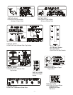
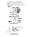
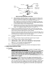
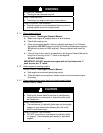
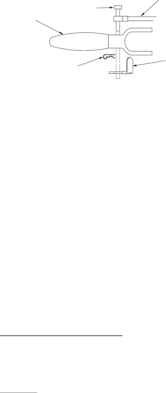
FIG. 11
DRIVE LEVER HARDWARE LOCATION
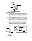
d) Adjust brakes by adjusting wingnut on upper end of each brake rod so
that when brakes are engaged there is approximately 1/4” of clearance
between ends of drive levers and handle grips (See Figure 10)
Note: Adjustment should allow the brakes to be engaged, yet allow the
neutral lock/park brake latches to be moved into the park brake position,
if not the brake linkages must be adjusted again.
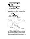
e) Squeeze the drive levers and move both neutral lock/park brake latches
into the neutral lock position. Mower should move forward and backward
freely, if not, readjust as stated in Sections 3.11c and 3.11d.
3.12 Route the long unattached wiring harness lead, up the left hand side of the
handle and connect the two terminals (in any order) to the operator presence
control switch terminals underneath the control console.
Fasten the lead to the handle with two small wire ties from the bolt bag, one at
the upper end of the handle next to the console, and one at the very lower end
of the handle where it attaches to the fuel tank support.
3.13 If machine is shipped without muffler installed, install muffler with hardware
provided.
3.14 For Briggs and Stratton Engines install debris guard to top of engine.
3.15 Service Engine: Refer to Engine Owner’s Manual.
3.16
GREASE UNIT: NOTE:
UNIT IS NOT GREASED AT THE FACTORY.
Refer to 5.1.13, for locations and grease amounts.
3.17 Follow pre-start instructions as outlined in 4.2.
3.18 Perform any needed adjustments as outlined in the Adjustment Section.
4. OPERATION INSTRUCTIONS
4.1 Controls
4.1.1 Operator Presence Control (OPC) Levers: Located on the upper handle
assembly directly above the handle grips.
When these levers are depressed,
the OPC system senses that the operator is in the normal operator's
position.
When the levers are released, the OPC system senses that the
operator has moved from the normal operating position
and will kill the
engine if either the transmission shift lever is
not in the neutral
position or the
blade clutch is engaged
.
4.1.2 Drive Levers: Located on each side of the upper handle assembly directly
below the handle grips. These levers individually control the clutching action of
the wheel drive belts and brakes. When the drive levers are all of the way
down, the wheel drive belts engage and the brakes disengage. Squeezing the
left or right hand drive lever causes the left hand or right hand wheel to slow
down or stop, which makes the machine turn to the left or right respectively.
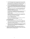
Drive Linkage
Left Side
Shown
Reference for
Position Only
Neutral
Lock/Park
Brake Latch
Drive
Lever
Clevis Pin
Hairpin