


- 14 -
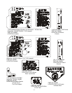
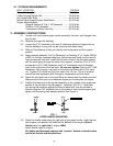
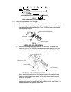
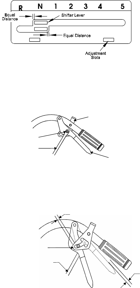
FIG. 8
THIS CLEARANCE SHOULD BE EQUAL
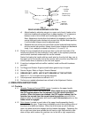
3.11 Install and adjust wheel drive linkages.
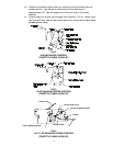
a) Screw threaded end of drive linkages into swivels in wheel drive idler arms.
b) Insert clevis pin from bolt bag through drive linkage, lever and slot in the
neutral lock/park brake latches (See Figure 9). Make proper adjustments
before adding hairpins.
FIG. 9
LEVER AND ROD ADJUSTMENT
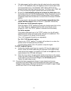
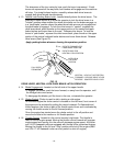
c) Adjust drive linkage length by threading into or out of the swivel until
there is a 3/16” to 1/4” clearance between the linkage assembly and the
bottom of the slot in the neutral lock/park brake latch. (See Figure 10)
FIG. 10
NEUTRAL LOCK LEVER CLEARANCE
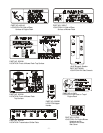
Note: Neutral lock/park brake latch clearance should be checked when
there is a slight upward force placed on the drive levers to remove any
“slack” in the linkage.
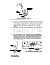
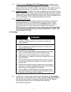
After clevis pin has been inserted, install hairpin into hole on the clevis pin
between the neutral lock/park brake latch and drive lever (See Figure 11).
Repeat procedure on opposite side of unit.
Clevis Pin
Drive Linkage
Neutral Lock/Park Brake Latch
Drive Lever
1/4” Clearance
3/16” TO 1/4”
Drive Linkage
Neutral Lock/ Park
Brake Latch