


- 14 -
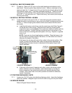
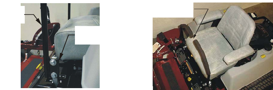
3.5 INSTALL SEAT RETAINING ROD.
3.5.1 Tilt seat up. Remove 5/16” nyloc nut from bolt attaching seat retaining rod to
seat frame. Remove ignition keys attached to bolt. Remove retaining rod from
seat and insert the “L” shaped end of the rod into the hole directly above the left-
side hydraulic pump (the “L” must be positioned pointing up). Position the seat
retaining rod to the outside of the mounting tab on the seat frame and secure
with 5/16” x 1” bolt and nyloc nut. Tighten until snug, then loosen just enough so
the rod pivots freely.
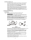
3.6 INSTALL MOTION CONTROL LEVERS.
3.6.1 Loosen and remove the two (2) 3/8” x 1” bolts and spring disc washers which
attach the motion control levers to the control arm shafts for shipping and the two
(2) 3/8” x 1” bolts and spring disc washers which are screwed into the control
arm shafts.
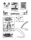
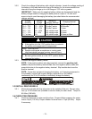
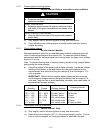
a) Install the left motion control lever onto the control arm shaft (See Figure 2)
on the left side of the console. Place the lever (with the mounting plate
towards the rear) on the outside of the control arm shaft and secure with the
bolts and washers. Position the lever so the bolts are in the center of the
slots on the lever mounting plate and tighten until snug. Repeat on opposite
side of unit.
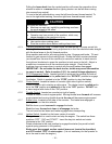
NOTE: There are two lever height options available. Place the levers in the
top two holes to increase height of the levers, or in the bottom two holes to
decrease the height of the levers.
If the levers do not align with each other, when in the neutral position, (See
Figure 3) loosen the hardware and make the appropriate adjustment by
sliding/tilting the lever(s) forward or backward until properly aligned and
tighten hardware.
FIGURE 2 FIGURE 3
CONTROL ARM SHAFT LEVER ALIGNMENT
b) If the ends of the levers hit against each other, while in the drive position
(levers rotated in as far as possible), make adjustments by moving the
levers outwards to the neutral lock position and carefully bending them
outward. Move them back to the drive position and check for clearance,
repeat if necessary.
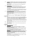
3.7 POSITION DISCHARGE CHUTE
3.7.1 Loosen two (2) 5/16” nyloc nuts attaching discharge chute. Lower the discharge
chute into position. Retighten nyloc nuts until chute is snug but can pivot freely.
3.8 SERVICE ENGINE
Refer to Engine Owner’s Manual.
MOUNT PLATE TO
THE REAR & OUTSIDE
OF ARM SHAFT
MOTION
CONTROL
LEVER
LEVERS IN
A
LIGNMENT