


Maintenance
Adjustments
Note: Disengage PTO, shut off engine, wait for
all moving parts to stop, engage parking brake, and
remove key before servicing, cleaning, or making any
adjustments to the unit.
Deck Leveling
1. Position mower on a at surface.
2. Stop engine, wait for all moving parts to stop, and
remove key. Engage parking brake.
3. Check tire pressure in drive tires.
For Units Equipped With Turf Tires: The drive
tires should be inated to 13 psi (90 kpa).
For Units Equipped With Bar-Lug Tires: The
drive tires should be inated to 9 psi (62 kpa).
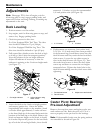
4. Fully extend the cylinder to raise the deck as high
as it will go (this is also the transport position).
Note the position of the cut height indicator.
Adjust the indicator if necessary so that the
indicator is pointing to the 5 inch cut height mark
(see Figure 17).
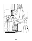
Figure 17
1. Cut height indicator
2. Adjust indicator using
these screws
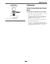
5. Lower the deck to the 4 inch cut height position
and remove ignition key. Orient the blades
longitudinally with respect to the machine. Stand
a wooden block approximately 5 inches tall next
to the front blade tip of the center blade; mark the
location of the blade tip on the block. Remove the
block and measure height on the block, it should
be 4 inches. Repeat this process for the rear blade
tip of both the left and right blades, those should
measure 4 1/4 inches to give the recommended
1/4 inch positive rake (see Figure 18).
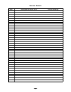
Figure 18
1. 4 1/4 inches
2. 4 inches
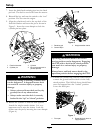
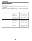
6. If adjustments are necessary, four socket head
5/16-18 x 1-1/4 inch screws have been provided
in the literature bag. Install these screws into the
deck lift arms until they touch the hex head deck
chain screws. Loosen the top chain screws in
slots in the deck lift arms (see Figure 19). Turn
the socket head screws to move the deck chain
screws up and down to correct the cut heights
measured above. Tighten the chain bolts in the
deck lift arms making sure they don’t move while
tightening.
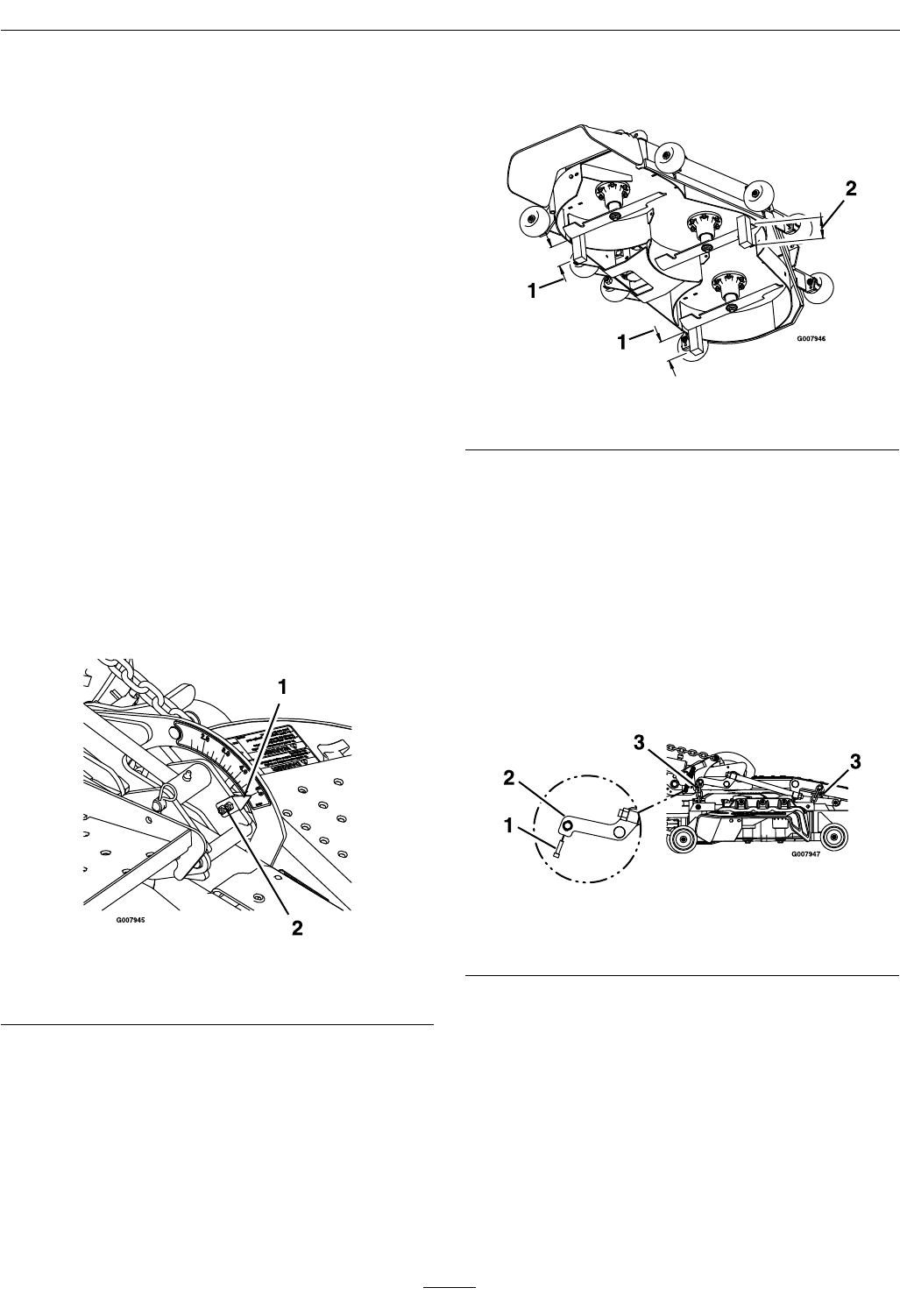
Figure 19
1. Socket head screw
3. Adjust screw and locknut
2. Deck lift arms
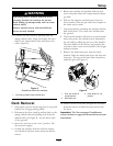
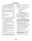
Caster Pivot Bearings
Pre-load Adjustment
Remove dust cap from caster and tighten nyloc nut
until washers are at. Back the nyloc off 1/4 of a
turn to properly set the pre-load on the bearings.
Note: If disassembled, make sure the spring washers
are reinstalled as shown in Figure 20.
20