


- 18 -
4.3.2 Stopping Engine: Lock drive levers in neutral, disengage PTO, move speed
control lever to neutral, and engage park brake. Move throttle to the “midway”
position. Allow engine to run a minimum of 15 seconds. Rotate ignition switch
to “Off” position. Remove key to prevent children or other unauthorized persons
from starting engine.
Close fuel shut-off valve when machine will not be used for a few days, when
transporting, and when the unit is parked inside a building.
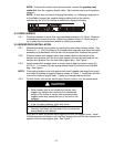
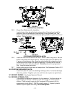
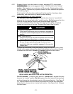
4.3.3 Drive Lever/Neutral Lock Latch Operation:
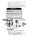
For Standard Pistol Grip Handles: To lock the drive levers in “neutral lock”,
squeeze the drive levers back to the “neutral” position (Do Not squeeze the drive
levers all the way back as this will cause the drive wheels to go into
full reverse direction). Place thumbs on the upper portion of the neutral lock
latches and move them to the rear. Release drive levers (See Figure 4).
CAUTION
POTENTIAL HAZARD
♦ If the neutral lock latches are not completely engaged the
drive levers could unexpectedly slip into the forward drive
position.
WHAT CAN HAPPEN
♦ If the drive levers slip into the drive position the unit could
lurch forward and cause injury or property damage.
HOW TO AVOID THE HAZARD
♦ Be sure the pins protruding through the slots of each
neutral lock latch are completely engaged in the rear slot
of each latch.
To place the drive levers in the drive position, firmly hold the drive levers, place
thumbs on the upper portion of the neutral lock latches and move them forward
to release the drive levers. Slowly and carefully release the drive levers.
FIGURE 4
DRIVE LEVER, NEUTRAL LOCK LATCH OPERATION
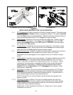
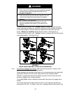
For ECS Handles: To lock the drive levers in “neutral lock”, squeeze the drive
levers to the “neutral” position (Do Not squeeze the drive levers all the way back
as this will cause the drive wheels to go into full reverse direction). See Figure 5
(a). Place thumbs on the inner lobe of the neutral lock latches and rotate them
under the drive levers into the “neutral lock” position. See Figure 5 (b). Release
the drive levers.