


- 15 -
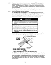
NOTE: The baffle is labeled “HOT” and “COLD”. The oil level varies with the
temperature of the oil. The “HOT” level shows the level of oil when it is at 225°F
(107°C). The “COLD” level shows the level of the oil when it is at 75°F (24°C). Fill
to the appropriate level depending upon the temperature of the oil. For example:
If the oil is about 150°F (65°C), fill to halfway between the “HOT” and “COLD”
levels. If the oil is at room temperature (about 75°F (24°C)), fill only to the “COLD”
level.
3.9 GREASE UNIT:
NOTE: UNIT IS NOT GREASED AT THE FACTORY.
Refer to Maintenance Section 5.1.14 for grease zerk locations and grease amounts.
3.10 FAMILIARIZE YOURSELF WITH THE CONTROLS.
See Controls Section 4.1.
3.11 FOLLOW PRE-START INSTRUCTIONS.
See Pre-Start Section 4.2.
3.12 PERFORM NECESSARY ADJUSTMENTS.
See Maintenance and Adjustment Section 5.
4. OPERATION INSTRUCTIONS
4.1 Controls
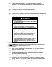
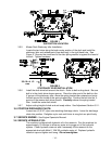
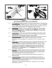
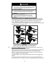
4.1.1 Operator Presence Control (OPC) Levers: Located on the upper handle
assembly directly above the handle grips. See Figure 3. When these levers
are depressed, the OPC system senses that the operator is in the normal
operator's position. When the levers are released, the OPC system senses
that the operator has moved from the normal operating position and will kill
the engine if either the speed control lever is not in the neutral position or the
PTO is engaged.
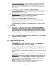
4.1.2 Drive Levers: Located on each side of the upper handle assembly directly below
the handle grips. See Figure 3. These levers individually control the speed and
direction of each drive wheel. When the speed control lever is moved out of the
neutral position and the neutral lock latches are moved into the drive position, as
shown in Figure 3, and the drive levers are released, the drive wheels are
engaged in the forward direction.
Squeezing the left hand and/or right hand lever causes the left hand and/or right
hand drive wheel respectively to slow down, stop, or reverse, depending on how
far each drive lever is “squeezed”. Squeezing the drive levers beyond the neutral
position causes the drive wheels to engage in the reverse direction regardless of
the position of the neutral lock latches and the speed control lever.
4.1.3 Neutral Lock Latches: These latches allow the operator to lock the drive levers in a
“neutral” position where the drive wheels are not engaged in either a forward or
reverse direction. See Figure 3.