


Operation
6. Pull the spring loaded idler back and slip the belt
over the top spindle deck sheave.
7. Install the plastic belt cover. On 60 inch and 66
inch units the outside end of the cover is slotted
and can slip between the two washers on the belt
shield stud. The plastic knob does not need to
be removed. On 72 inch and 52 inch units the
cover has a hole, and the plastic knob must be
installed after the cover has been positioned. The
original belt cover stud must be removed on
52 inch units.
8. For Units Serial Number 600,000 and Higher
with Triton Decks: Adjust position of dog leg
bafe to match the intake of the Ultra Vac blower
bafe adjusted too wide may allow objects to be
thrown from under deck. Bafe adjusted too
narrow may cause plugging issues.
All Units: Slip the upper end of the tube
assembly into the hood opening. Slide the lower
end of the tube assembly over the blower outlet
and align the notch with the tube latch. Latch the
tube to the blower.
Note: The removable weights are heavy. Use
care when lifting. Make sure that you can hold the
weight securely before lifting. Use caution when
positioning your hands so that you Do Not set
the weight down on your hands or ngers.
9. Install the removable weight assemblies over
the caster arms. On 52 inch and 60 inch Lazer
Z AS machines and 60 inch Lazer Z machines
serial number 599,999 and lower, one weight has
a wide mounting bracket and one has a narrow
bracket. They will only t the machine one way.
Weights for the 60 inch Lazer Z serial number
600,000 and higher, 60 inch Lazer Z XP, 60 inch
Lazer Z XS and all 66 inch and 72 inch units are
interchangeable left and right.
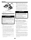
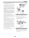
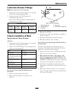
10. Install a clevis pin and hairpin on each caster
weight to retain them (see Figure 7).
Figure 7
1. Clevis Pin
2. Hairpin
11. Units with removable oorpan weight:
Tighten knob on weight assembly until the weight
is clamped securely to the caster arm.
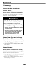
12. Hook weight plate assembly over the top of the
weight mounting plates and secure with two
hairpins as shown in Figure 8).
Figure 8
1. Weight Plate Assembly 2. Hairpin
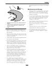
Note: The portions of the Ultra Vac bagger that
are not bolted to the mower are designed to be
installed or removed in their entirety. Do Not
operate the mower with only a portion of the
Ultra Vac installed.
15