


Setup
Figure 7
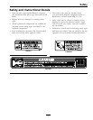
1. Replacement decals
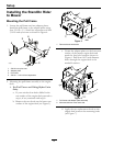
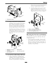
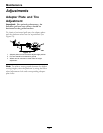
e. Align the pull frame and adapter plate
assembly to the rear surface of the engine
deck. Measure the distance from the
bottom of the pull frame to the ground.
Choose the mount holes that will attain a
distance approximately 8 inches (20 cm).
Install the mount brackets to the mower
engine deck using two 3/8-16 x 1 1/4 inch
hex capscrews, two back-up plates, and
two 3/8-16 inch nyloc nuts as shown in
Figure 8).
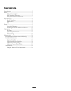
Figure 8
1. 3/8-16 x 1 1/4 inch hex
capscrews
3. Backup plates
2. Pull frame and adapter
plate assembly
4. 3/8-16 inch nyloc nuts
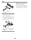
B. For Turf Tracer HP and Metro HP Units:
a. Align the pull frame and adapter plate
assembly to the rear surface of the engine
deck. Measure the distance from the
bottom of the pull frame to the ground.
Choose the mount holes that will attain a
distance of approximately 8 inches.
b. Install the adapter plates to the mower
engine deck using two 3/8-16 x 1/4
inch hex capscrews and two 3/8-16 inch
anged nyloc nuts as shown in Figure 9.
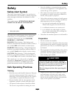
Figure 9
1. 3/8-16 x 1/4 inch hex capscrews
2. Pull frame and adapter plate assembly
3. 3/8-16 inch anged nyloc nuts
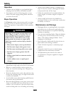
Mounting the Pull Arm and Platform
For Turf Tracer, Turf Tracer HP, Metro HP, and
Viking Hydro Units:
1. Locate the pull arm assembly. Align the pull
arm assembly with the pull frame as shown in
Figure 10. Squeeze the quick connect pins on
the pull arm assembly and attach the pull arm
assembly to the pull frame.
11