


Maintenance
Voltage
Reading
Percent
Charge
Maximum
Charger
Settings
Charging
Interval
12.6 or
greater
100%
16 volts/7
amps
No
Charging
Required
12.4 – 12.6 75–100%
16 volts/7
amps
30 Minutes
12.2 – 12.4 50–75%
16 volts/7
amps
1 Hour
12.0–12.2 25–50%
14.4 volts/4
amps
2 Hours
11.7–12.0 0–25%
14.4 volts/4
amps
3 Hours
11.7 or less
0%
14.4 volts/2
amps
6 Hours or
More
Check Safety Interlock
System
Service Interval: Before each use or daily
Note: To prevent engine cut-outs on rough terrain
the seat kill switch has a 1/2 second delay.
1. Check starting circuit. Starter should crank with,
parking brake engaged, PTO disengaged and
motion control levers moved out in the neutral
lock position. The operator does not need to be
in the seat to start the engine.
Try to start with operator in seat, parking brake
disengaged, PTO disengaged and motion control
levers in the neutral lock position - starter must
not crank.
Try to start with operator in seat, parking brake
engaged, PTO engaged and motion control
levers in the neutral lock position - starter must
not crank.
Try to start with operator in seat, parking
brake engaged, PTO disengaged, and the left
motion control lever in, starter must not crank,
repeat again with the right lever in, then with
both levers in - starter must not crank.
2. Check the kill circuits. Run engine at one-third
throttle, disengage parking brake and raise off
of seat (but do not get off of machine) engine
must initiate shutdown after approximately 1/2
second has elapsed (seat has time delay kill switch
to prevent cut-outs on rough terrain).
Run engine at one-third throttle, engage PTO
and raise off of seat (but do not get off of
machine) engine must initiate shutdown after
1/2 second has elapsed.
Run engine at one-third throttle, with brake
disengaged, move levers in and raise off seat (but
do not get off of machine) engine must initiate
shutdown after 1/2 second has elapsed.
Again, run engine at one-third throttle, brake
engaged, and move left motion control lever in
- engine must initiate shutdown.
Repeat again moving the right lever in, then
moving both levers in - engine must initiate
shutdown whether operator is on seat or not.
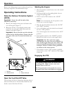
3. Check the PTO circuit. See the FR524, FR604,
and FR724 Operator’s manual to become familiar
with the deck operation. Open the folding
deck latches, disengage the park brake, move
the motion control levers in to neutral, and
disengage the PTO. Lower the deck until the
PTO switch arm is no longer depressing the PTO
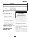
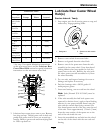
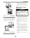
“kill” switch (see Figure 8).
Figure 8
Left Side—Inside of Hitch Shown
1. PTO “Kill” Switch
2. PTO Switch Arm
3. Lower deck until arm Does Not contact the switch.
Run the engine at half throttle and pull up on the
PTO engagement switch.
The PTO must not engage.
26