Setup
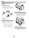
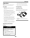
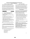
Figure 10
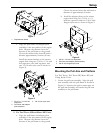
1. Pull arm assembly
3. Pull frame
2. Quick connect pins
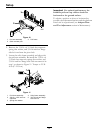
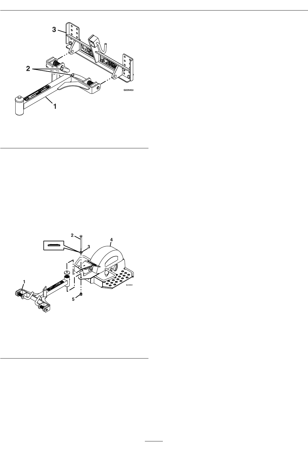
2. Remove the 3/8-16 x 4 3/4 inch hex capscrew.
spring disc washer, and 3/8-16 inch hex ange
side lock nut from the pivot hub.
3. Locate the sulky frame assembly and align with
the pull arm assembly. Re-install the 3/8-16 x 4
3/4 inch hex capscrew, spring disc washer, and
3/8-16 inch hex ange side lock nut removed in
step 1 as shown in Figure 11. Torque to 35-38
ft-lb (47-52 N-m).
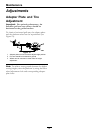
Figure 11
1. Pull frame assembly 4. Sulky frame assembly
2. 3/8-16 x 4 3/4 inch hex
capscrew
5. 3/8-16 inch hex ange
side lock nut
3. Spring disc washer
Important: For optimal performance, the
StandOn pull arm top surface should be
horizontal to the ground surface.
To obtain a position as close to horizontal as
possible, the adjustment brackets and the platform
wheel can be repositioned (see Adapter Plate
and Tire Adjustment section in Maintenance).
12