


Maintenance
Note: Blade driver ats must be aligned with the
ats on the shaft when installing blade on the
mower deck.
6. Lower the mower deck to the operation position
(see section Lowering the Mower Deck to the
Operation Position).
WARNING
Operating a mower deck with loose or
weakened blade bolts can be dangerous. A
loose or weakened blade bolt could allow a
blade rotating at a high speed to come out
from under the deck, causing serious injury
or property damage.
• Replace the blade bolt after striking a
foreign object.
• Use only genuine Exmark replacement
parts.
• Do Not lubricate the threads of the bolt
or spindle before assembly.
• Torque the blade bolt to 85-110 ft-lb
(115-149 N-m).
• Torque the shear bolts to 80-100 in-lb
(922-1130 N-cm).
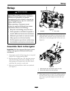
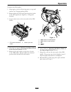
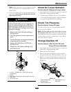
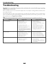
Figure 12
1. 1/2-20 x 2 1/4 blade bolt— torque to 85-110 ft-lb
(115-149 N-m).
2. Washer
3. Shear bolts—torque to 80–100 in-lb (922-1130 N-cm)
4. Blade driver
5. 1/4-20 nyloc nuts
Check for Loose Hardware
Service Interval: Before each use or daily
1. Stop engine, wait for all moving parts to stop, and
remove key. Engage parking brake.
2. Visually inspect machine for any loose hardware
or any other possible problem. Tighten hardware
or correct the problem before operating.
Check Tire Pressures
Service Interval: Every 40 hours
The front caster tires are semi-pneumatic and Do
Not need to be inated.
Note: Do Not add any type of tire liner or foam
ll material to the tires. Excessive loads created by
foam lled tires may cause failures to the hydro drive
system, frame, and other components. Foam lling
tires will void the warranty.
Change Gearbox Oil
Service Interval: After the rst 50 hours
Every 100 hours thereafter
1. Stop engine, wait for all moving parts to stop, and
remove key. Engage parking brake.
2. Place unit on a level surface.
3. Remove the gearbox and drive shaft assembly
from the mower deck. Retain hardware for re-use.
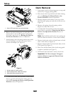
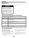
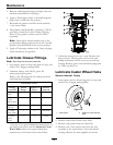
4. Remove the large oil drain plug on the front of
each of the three gearbox sections and drain oil
(Figure 13).
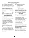
Figure 13
1. Small magnetic plugs
(front and back)
3. Small magnetic plug
(front only)
2. Large oil drain/ll plug
15