Maintenance
Check Wheel Hub Locknuts
Service Interval: After the rst 100 hours
Every 500 hours thereafter
Torque to 210–250 ft-lb (285–339 N-m).
Check Wheel Lug Nuts
Service Interval: After the rst 100 hours
Every 500 hours thereafter
Torque to 90–95 ft-lb (122–129 N-m) cross pattern.
Fuel Tank — Mounting
Hardware Specications
Service Interval: As required
When installing the nuts on the fuel tank studs, fully
tighten the nyloc nut and back off 1/2 turn. This
allows for normal fuel tank expansion and contraction
with changes in temperature and fuel levels.
Thread Locking Adhesives
Thread locking adhesives such as “Loctite 242”
or “Fel-Pro, Pro-Lock Nut Type” are used on the
following fasteners:
• Pump drive sheave set screws.
• Square head setscrews on Hydro pump control
arms.
• Sheave retaining bolt in the end of engine
crankshaft, blower shaft and jackshaft.
• Caster wheel spacer nuts.
• Fuel tank bulkhead tting nuts.
Adhesives such as “Loctite RC/609 or RC/680” or
“Fel-Pro Pro-Lock Retaining I or Retaining II” are
used on the following:
Fuel tank studs, where studs are inserted into tank.
Dielectric Grease
Dielectric grease is used on all blade type electrical
connections to prevent corrosion and loss of contact.
Adjustments
Note: Disengage PTO, shut off engine, wait for
all moving parts to stop, engage parking brake, and
remove key before servicing, cleaning, or making any
adjustments to the unit.
PTO Drive Belt Tension
Self-tensioning - No adjustment necessary.
Pump Drive Belt Tension
Self-tensioning - No adjustment necessary.
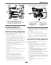
PTO Belt Replacement
1. Stop engine, wait for all moving parts to stop, and
remove key. Engage parking brake.
2. With engine “off ”, engage PTO lever, then
remove the hairpin and clevis pin at the bottom
of the PTO brake band.
3. Rotate the brake band upwards out of the way of
the belts keeping clear of the belt drive.
4. Disengage PTO lever.
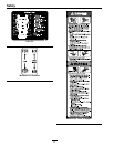
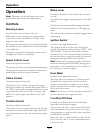
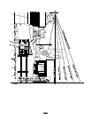
5. Loosen belt guides “A” and “B” (See Figure 8).
6. Remove current belts
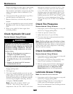
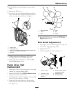
7. Route new belts onto sheaves as shown in the
decal located on the back of the left drive shield
(see Figure 8).
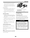
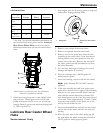
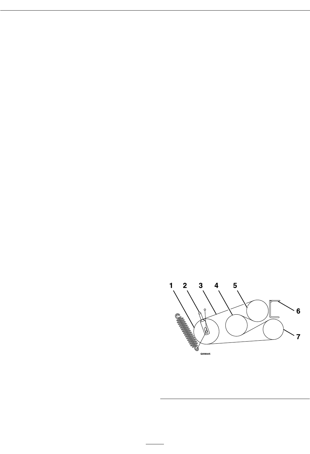
Figure 8
1. Idler 5. Engine
2. Belt Guide “B” 6. Belt Guide “A”
3. PTO Belt
7. Blower
4. Jackshaft
8. Engage the PTO lever
9. Rotate brake band back down into original
position
28