


Maintenance
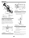
Shifter Detent Adjustment
Transmission shifter detent can be adjusted
by adjusting the setscrew on the back side of
transmission located just behind the neutral start
switch. Turn setscrew in (clockwise) to hold the
transmission shifter more positively in each gear and
to increase the force on the lever required to shift
gears.
Turn setscrew out (counterclockwise) to decrease
force on lever required to shift gears. Factory setting
is to turn setscrew all the way in then back out 1 1/2
turns.
Important: Screwing setscrew in too far will
prevent the transmission from shifting.
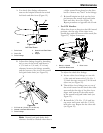
PTO Safety Switch
Adjustment
1. Stop engine and wait for all moving parts to stop.
Engage parking brake. Remove key or spark plug
wire(s).
2. With the blades disengaged and the bellcrank
touching the engine deck, adjust the blade safety
switch (if needed) until the bellcrank depresses
the plunger by 1/4 inch (.64 cm).
3. Be sure the bellcrank does not contact the switch
body to prevent damage to the switch.
4. Retighten switch mounting hardware.
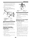
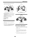
Handle Height Adjustment
The handle can be pivoted to allow positioning in
one of the three holes allowing various adjustments
for operator comfort (see
Figure 26).
To adjust the handle height:
1. Remove the bottom mounting hardware on each
side of the handle.
2. Pivot the handle to one of the three positions.
3. Re-install hardware and tighten.
Important: If the handle height position is
changed, it will be necessary to readjust the
drive and brake linkage (see Check Brake and
Wheel Drive Linkage Adjustment section in
Operation.)
Figure 26
1. Upper Handle 3. Adjustment Holes
2. Upper Hole
4. Fuel Tank Support
Note: Adjustment Holes are actually in the side
of the fuel tank support.
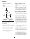
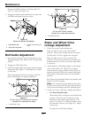
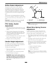
Wheel Drive Spring Tension
Adjustment
It may be necessary to increase wheel drive belt
tension under certain operating conditions such as,
wet grass, hilly terrain, or while pulling a sulky.
1. Stop engine and wait for all moving parts to stop.
Engage parking brake. Remove key or spark plug
wire(s).
2. Disengage neutral lock/park brake latches and
release drive levers to lower spring force.
3. Remove the 5/16-18 inch whizlock nut securing
the adjustment bolt to the drive wheel shield.
Locate bolt assembly in the desired position as
follows:
• Position A-Normal Conditions
• Position B-More Severe
• Position C-Most Severe
Note: Lever force is lowest with bolt assembly
in Position A and will increase in Positions B and
C (see
Figure 27).
33