


Maintenance
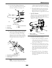
8. With the jack, raise or lower the back end of the
engine deck so that two axle adjustment bolts can
be reinstalled in desired hole location. A tapered
punch can be used to help align the holes.
9. Retighten all four bolts, lower unit and remove
jack.
10. Install mower deck belt shield.
11. Adjust wheel drive and brake linkages as
required (see Brake and Wheel Drive Linkage
Adjustment section).
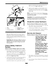
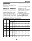
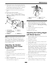
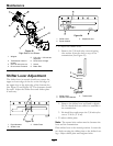
Figure 10
1. Axle Pivot Bolt
5. Position C
2. Axle Adjustment Holes
(Located in the side of
the rear deck.)
6. Position D
3. Position A 7. Position E
4. Position B 8. Place jack here
Note: The axle positions are in 1/2 inch (1.3 cm)
increments and the large caster spacers are 1/2
inch (1.3 cm) thick. Therefore, by adjusting the
same number of 1/2 inch (1.3 cm) caster spacers as
axle hole positions the blades will retain the same
front-to-back tip (rake).
Adjusting the Number
of Spacers below Caster
Support Hub
1. Stop the machine and move the drive levers to
the neutral lock position.
2. Disengage the PTO.
3. Place the drive levers in the “park brake” position.
4. Push down on handles to lift front casters off the
ground.
5. Support with jackstands.
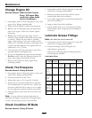
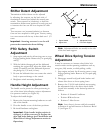
6. Remove “quick pin” from one caster and remove
caster from hub (see Figure 11).
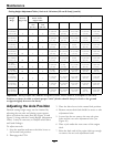
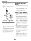
Figure 11
1. Four 1/2 inch (127 mm)
spacers
3. 3/16 inch (4.8 mm)
spacer
2. Quick Pin 4. Caster support
7. Adjust the number of 1/2 inch spacers between
bottom of hub and caster yoke to obtain the
desired cutting height from the Cutting Height
Adjustment Table in the Adjusting the Cutting
Height section.
8. Install remaining spacers on top of hub.
9. Install “quick pin”.
10. Repeat for other caster.
Adjusting the Cutting Height
with Blade Spacers
1. Stop the machine and move the drive levers to the
neutral locked position.
2. Disengage the PTO.
3. Engage the park brake.
4. Stop the engine, remove the key and wait for all
moving parts to stop.
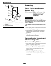
5. Blades may be adjusted for cutting height by using
the four 1/4 inch (.64 cm) spacers found on the
blade spindle bolts (factory setting is two above
and two below). This allows a 1 inch (2.5 cm)
range in 1/4 inch (.64 cm) increments of cutting
height in any axle position. The same number
of blade spacers must be used on all blades to
achieve a level cut (two above and two below, one
above and three below, etc.).
6. Raise front of deck and support with jack stands.
7. Hold blade bolt on bottom and loosen spindle
nut on top.
8. Adjust number of spacers between bottom of
spindle and blade as indicated in the Cutting
27