


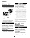

Maintenance
or when a brake component has been removed or
replaced.
1. Drive the machine onto a level surface.
2. Disengage the blade control switch (PTO), move
the motion control levers to the neutral locked
position and set the parking brake.
3. Stop the engine, wait for all moving parts to stop,
and remove the key.
4. Setup the machine to be pushed by hand (see
Drive Wheel Release Valves in the Operation
section).
5. Raise the back of the machine up and support the
machine with jack stands.
CAUTION
Raising the mower deck for service or
maintenance relying solely on mechanical
or hydraulic jacks could be dangerous. The
mechanical or hydraulic jacks may not be
enough support or may malfunction allowing
the unit to fall, which could cause injury.
Do Not rely solely on mechanical or hydraulic
jacks for support. Use adequate jack stands
or equivalent support.
6. Engage/disengage the brake and check each drive
tire to make sure each brake engages/disengages.
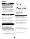
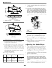
7. If adjustment is necessary, loosen the jam nut
from the yoke on the side that needs adjustment.
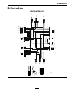
Remove the hairpin and clevis pin (see Figure 29).
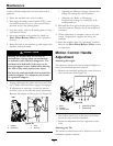
Figure 29
1. Hairpin 3. Yoke
2. Clevis pin
4. Jam nut
• Adjusting the Brake to Engage: Shorten the
linkage by turning the yoke clockwise.
• Adjusting the Brake to Disengage:
Lengthen the linkage by turning the yoke
counterclockwise.
8. Reinstall the clevis pin and hair pin and tighten
down the jam nut. Repeat step 6 and readjust if
necessary.
9. When adjustment is complete, remove the jack
stands or equivalent support and lower the
machine.
10. Place the machine into the “operating” position.
Refer to the Drive Wheel Release Valves section
in Operation.
Motion Control Handle
Adjustment
Adjusting the height:
The motion control levers can be adjusted higher or
lower for maximum operator comfort.
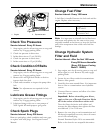
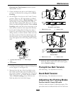
1. Remove the hardware holding the control lever to
the control arm shaft (Figure 30).
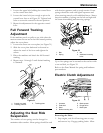
Figure 30
1. Bolts
4. Control arm shaft
2. Washer
5. Slotted hole
3. Control lever
2. Move the control lever to the next set of holes.
Secure the lever with the hardware.
3. Repeat the adjustment for the opposite control
lever.
Adjusting the Tilt
The motion control levers can be tilted fore or aft for
maximum operator comfort.
38