


7
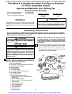
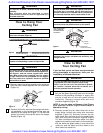
3. Screw the two threaded studs (supplied) into the
tapped holes in the hanger bracket.
4. Lift the ceiling cover up to the threaded studs and
turn until studs protrude through the holes in the
ceiling cover (Figure 13).
5. Secure the ceiling cover in place by sliding
lockwashers over the threaded studs and installing the
two knurled knobs (supplied). (Figure 13). Tighten the
knurled knobs securely until the ceiling cover fits
snugly against the ceiling and the hole in the ceiling
cover is clear of the downrod. Your fan is now wired to
be turned on and off from the fan switch.
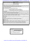
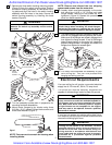
NOTE: CEILING COVER
OMITTED FOR CLARITY.
GROUND
WIRE
LISTED
WIRE
CONNECTOR (3)
GREEN WIRE
(GROUND) FROM
HANGER BRACKET
GREEN WIRE
(GROUND) FROM
HANGER BALL
WHITE SUPPLY
(NEUTRAL)
WHITE FAN
WIRE
BLACK SUPPLY
(HOT)
BLACK AND BLUE
FAN WIRES
Fi
g
ure 4
CEILING COVER
THREADED STUD
KNURLED KNOB
LOCKWASHERS (2)
Figure 12
Figure 13
Setting Remote Control
Operating Frequency
Your Emerson Remote Control Fan receiver and
transmitter can be set to operate at one of 16
different frequencies. In most cases you will not need
to change the factory set frequency. The frequency
should only need to be changed for one of the
following reasons:
a. Multiple fans in one location that you wish to
operate from one transmitter. (ALL fans should be
set at the same frequency.)
NOTE: Your Emerson Remote Control is designed
to operate from a distance up to 20 feet from the
fan. If you are operating multiple fans with one
transmitter you should be no more than 20 feet
from any of the fans to ensure that all fans will
respond at the same time.
b. Multiple fans in one location that you wish to
operate from different transmitters. (ALL fans set
to different frequencies.)
c. Interference with other household systems such as
your garage door opener.
NOTE: If you change the operating frequency,
you must change both the transmitter and
receiver to the same frequency. The remote
control will not operate unless both the transmit-
ter and receiver are set at the same frequency.
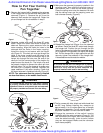
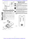
Setting Transmitter Frequency
1. Remove battery cover and the battery from the
transmitter. Locate the switch with four levers
numbered 1, 2, 3, 4, just above the battery
compartment (See Figure 14).
2. With a narrow blade screwdriver, change the
position of one or more of the four levers on the
switch. Note the positions of each of the four
levers by number; down is ON, up is OFF.
Setting Receiver Frequency
1. After electricity has been turned off at the main fuse
box, remove the switch housing assembly by
removing the three mounting screws (See Figure 6).
2. Disconnect the switch housing connector form the
motor connector by squeezing the latch and pulling
the connectors apart.
3. Remove the receiver from the switch housing and
locate the switch with four numbered levers (same
as transmitter). (See Figures 14 and 15).
4. Set the position of all four levers, ON or OFF to the
same position as those on the transmitter.
5. Install the receiver in the switch housing, push the
motor connector into the switch housing connector
and assemble the switch housing assembly to the
housing plate (See Figures 5 and 6).
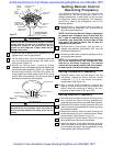
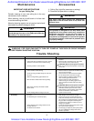
Check to see that all connections are tight, including
ground, and that no bare wire is visible at the wire
connectors, except for the ground wire. Do not
operate fan until blades are in place. Noise and fan
damage could result.
WARNING
!
To avoid possible fire or shock, make sure that the
electrical wires are completely inside the outlet box
and not pinched between the ceiling cover and the
ceiling.
WARNING
!
SUPPLY
GROUND
WIRE
Authorized Emerson Fan Dealer www.NovaLightingStore.com 800-860-1207
Emerson Fans Available at www.NovaLightingStore.com 800-860-1207