


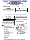
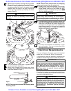
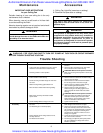
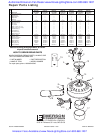
7. Remove the three switch housing mounting screws
(Figure 5) from the switch housing plate. Position
the switch housing assembly on the switch hous-
ing plate and align the holes in the switch housing
assembly with the holes in the plate. Secure the
switch housing assembly by installing the three
screws (Figure 6).
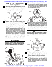
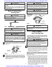
8. Turn fan assembly upside down in preparation for
mounting fan blade assemblies.
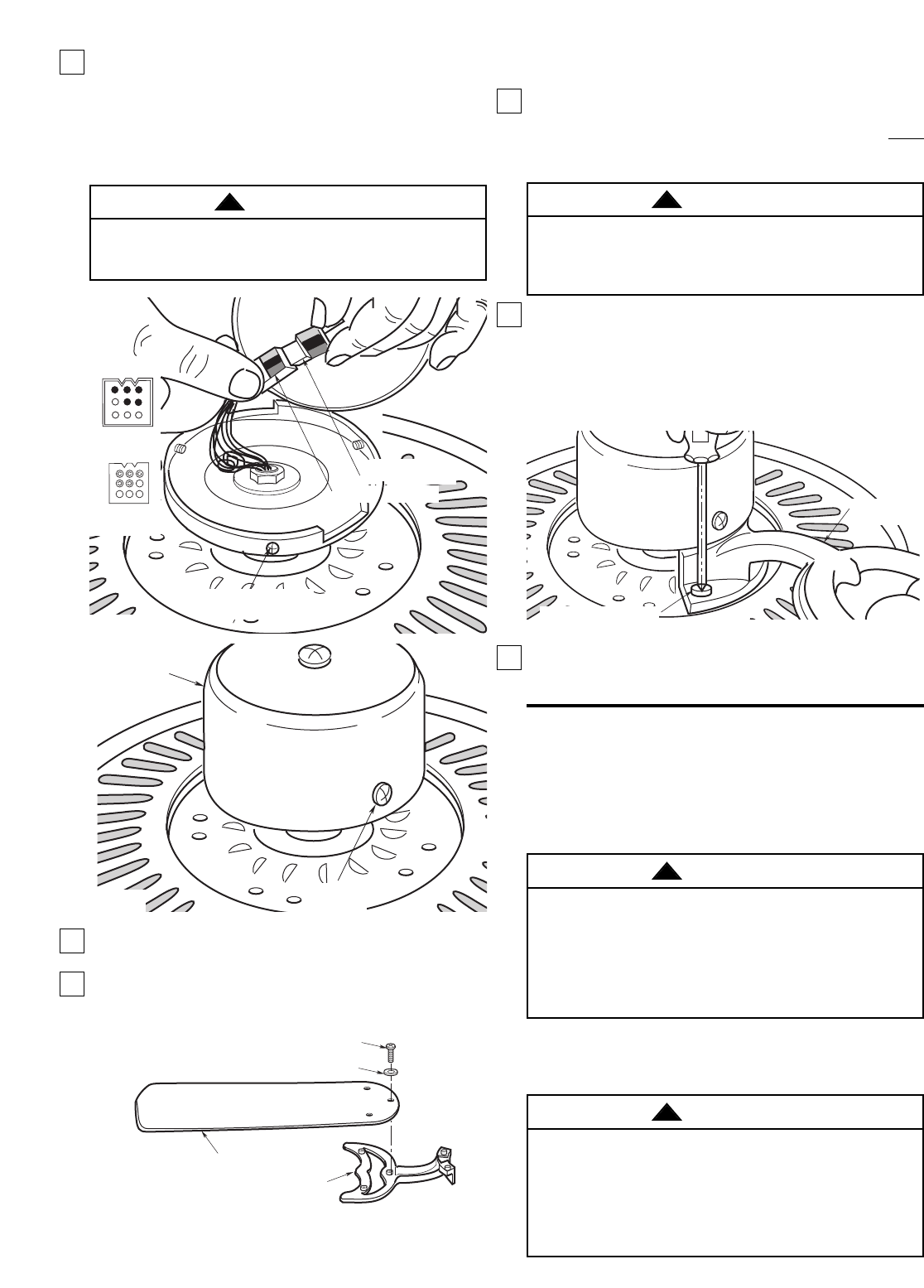
9. Mount blade flanges to fan blades using three
3/16-24 x 5/16” slotted Phillips blade screws and
three blade washers (Figure 7).
NOTE: Take care not to scratch fan housing when
installing blades.
The outlet box must be securely anchored and
capable of withstanding a load of at least 50 pounds.
If your fan is to replace an existing ceiling light fixture,
turn electricity off at the main fuse box at this time and
remove the existing light fixture.
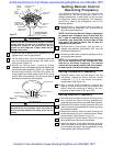
NOTE: Remove and discard the four shipping
spacers and screws from the motor hub.
10. Loosely attach one blade assembly to the motor
hub using two 1/4-20 x 1/2” Phillips oval head
flange screws. Make sure the screws are NOT
tightened. (Figure 8.) Repeat this procedure for
other four blade assemblies.
11. The blade flanges have an interlocking feature that
must be fully engaged before tightening the screw.
Make sure all the flanges are properly engaged and
then tighten the flange screws. If one of the flanges
does not seat properly on the motor hub, loosen the
adjacent flange screws, re-engage and reseat the
flanges, then tighten the screws again.
12. You have now completed the assembly of your
new ceiling fan. You can now proceed with
hanging and wiring your fan.
To reduce the risk of personal injury, do not bend the
blade flange when installing the blade flanges,
balancing the blades or cleaning the fan. Do not
insert foreign objects in between rotating fan blades.
BLADE
ASSEMBLY
BLADE FLANGE SCREWS
Figure 8
WARNING
!
5
Electrical Requirements
Your new ceiling fan will require a grounded electrical
supply line of 120 volts AC, 60 Hz, 15 amp circuit.
FAN BLADE
BLADE FLANGE
3/16-24 x 5/16" SLOTTED PHILLIPS
BLADE SCREW (3)
BLADE WASHER (3)
Figure 7
SWITCH
HOUSING
ASSEMBLY
MOUNTING
SCREWS (3)
Figure 6
To reduce the risk of fire, electric shock, or personal
injury, mount fan to outlet box marked acceptable for
fan support, and use screws supplied with outlet
box. Most outlet boxes commonly used for support
of light fixtures are not acceptable for fan support
and may need to be replaced. Consult a qualified
electrician if in doubt.
Turning off wall switch is not sufficient. To avoid
possible electrical shock, be sure electricity is
turned off at the main fuse box before wiring. All
wiring must be in accordance with National and
Local codes and the ceiling fan must be properly
grounded as a precaution against possible
electrical shock.
WARNING
!
WARNING
!
To avoid possible fire or shock, do not pinch wires
between the switch cup assembly and the switch
cup plate.
WARNING
!
SWITCH HOUSING
MOUNTING SCREW (3)
SWITCH HOUSING
CONNECTOR
MOTOR CONNECTOR
SWITCH CUP
CONNECTOR
MOTOR
CONNECTOR
Figure 5
Authorized Emerson Fan Dealer www.NovaLightingStore.com 800-860-1207
Emerson Fans Available at www.NovaLightingStore.com 800-860-1207