


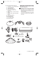
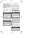
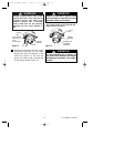
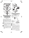
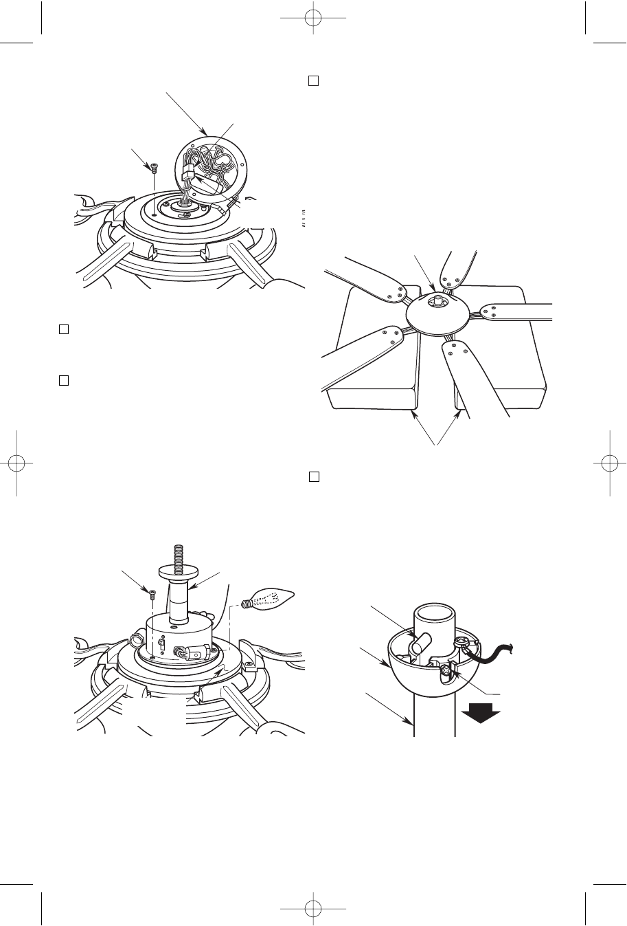
8. Remove and retain the three outer
screw/lockwashers from the light fitter
adapter (Figure 4).
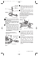
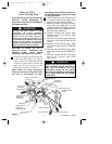
9. Position the light fitter assembly on the
light fitter adapter. Line up the three
holes on the light fitter with the
threaded holes in the adapter and
reinstall three screw/lockwashers
(previously removed) (Figure 5).
CAUTION: Before installing and
tightening the screws, be sure there are
no wires pinched between the light
fitter and the light fitter adapter.
7
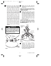
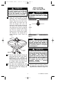
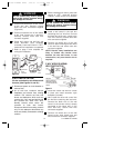
10. Position the top and bottom halves of
the styrofoam packaging side-by-side
on the floor with a six to eight inch gap
between the halves (Figure 6).
Carefully place the partially assembl-
ed ceiling fan on the styrofoam
halves, with the light fitter assembly
positioned in the gap and the fan
assembly resting on the fan blade
assemblies.
PARTIALLY
ASSEMBLED FAN
STYROFOAM PACKAGING
6 TO
8-INCH
GAP
Figure 6
REMOVE AND RETAIN
THREE PAN HEAD
SCREW/LOCKWASHERS
LIGHT FITTER
CONNECTOR
MOTOR
CONNECTOR
LIGHT FITTER
ASSEMBLY
Figure 4
REINSTALL THREE
PAN HEAD SCREW/
LOCKWASHERS
LIGHT FITTER
ASSEMBLY
LIGHT FITTER
ADAPTER
Figure 5
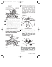
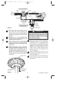
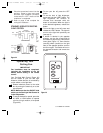
PIN
HANGER
BALL
SETSCREW
DOWNROD
Figure 7
11. Remove the hanger ball by loosening
the setscrew in the hanger ball until
the ball falls freely down the downrod
(Figure 7). Remove the pin from the
downrod, then remove the hanger
ball. Retain the pin and hanger ball for
reinstallation in step 16.
NOTE: If you have an eight-foot ceiling,
you will have to use the 8” downrod
(supplied) in order to maintain the
necessary blade-to-floor clearance of
seven feet.
U.L. Model No.: CF240
BP7359 VININGS CF240 9/19/07 11:13 AM Page 7