


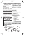
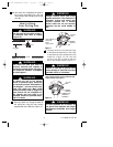
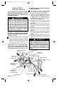
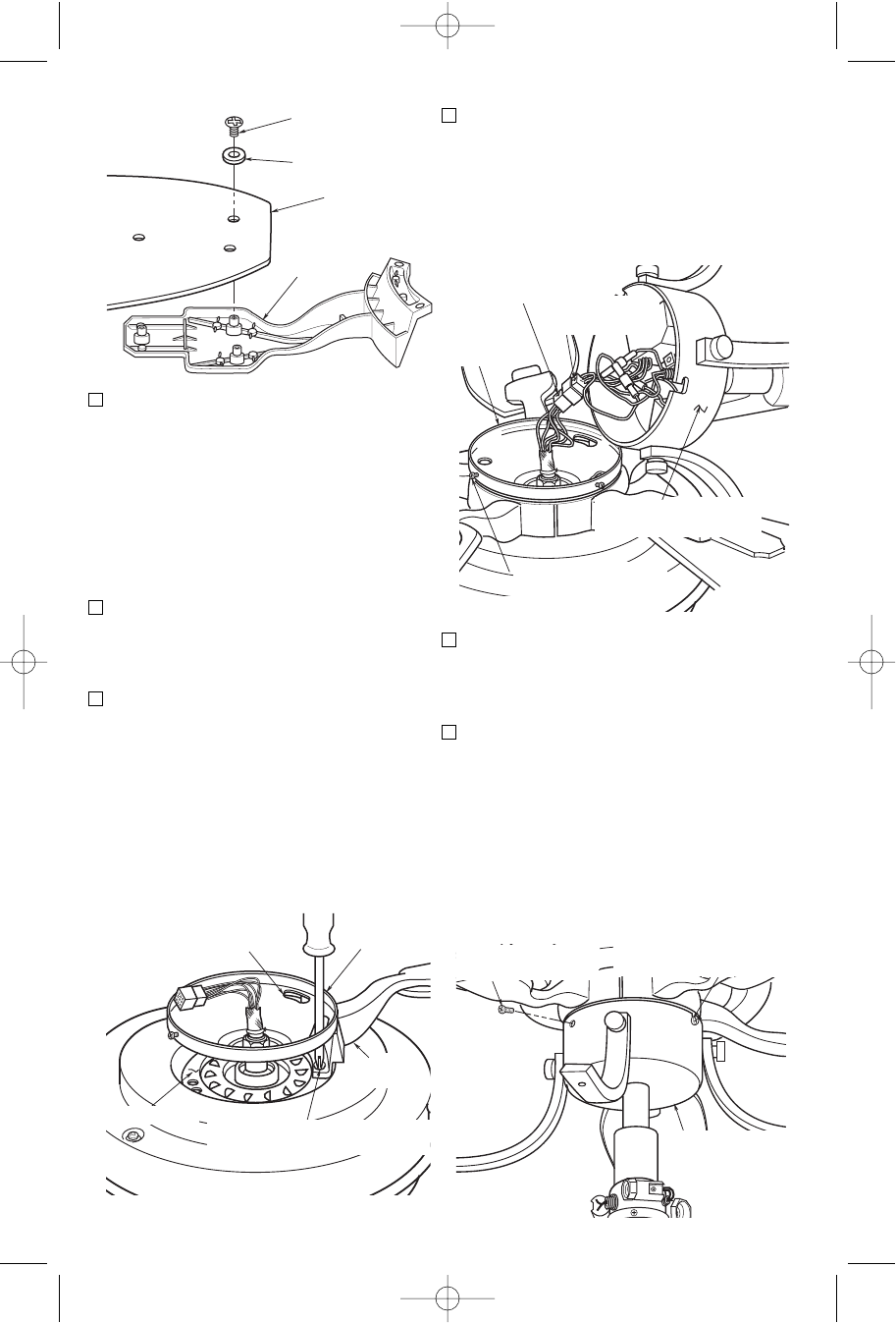
11. Engage the connector of the switch
housing/light fitter assembly with the
motor connector (Figure 8). The two
connectors are color-coded and must
be mated correctly (color-to-color)
before they can be engaged. Make
sure the connectors close properly.
12. Partially install two 8-32 x 7mm pan
head screws (supplied) into two of the
threaded holes in the side of the switch
housing plate (Figure 8).
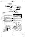
13. Position the two slots in the switch
housing/light fitter assembly over the
two 8-32 x 7mm screws (Figure 9).
Turn the switch housing assembly
clockwise and tighten the two screws.
Install another 8-32 x 7mm pan head
screw into the remaining hole to
secure the switch housing assembly.
NOTE: Do not pinch wires between the
switch housing assembly and the
switch housing plate.
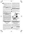
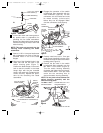
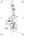
8. Turn the fan motor and housing assem-
bly upside down in preparation for
mounting the fan blade assemblies.
Remove and discard the three shipping
retainers securing the motor hub in the
motor housing.
NOTE: Take care not to scratch the fan
housing when installing the blade
assemblies.
9. Insert a 1/4-20 x 11mm pan head screw
with lockwashers into each of the two
recessed holes in one of the blade
flanges.
10. Align two of the threaded holes in the
motor hub with the two slots in the
switch housing plate (Figure 7).
Position the blade flange on the motor
hub so that the screws in the blade
flange align with the two threaded
holes in the motor hub. Tighten the two
screws securely. Repeat this proce-
dure for the remaining four blade
assemblies.
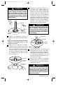
10-24 x 9mm TRUSS
HEAD SCREW (3)
FIBER WASHER (3)
FAN BLADE
BLADE
FLANGE
Figure 6
SWITCH
HOUSING
PLATE
SLOT FOR FLANGE
SCREW ACCESS
BLADE
FLANGE
1/4-20 x 11mm PAN HEAD
SCREWS WITH LOCKWASHER (2)
MOTOR HUB
Figure 7
INSTALL 8-32 x 7mm
PAN HEAD SCREW
TIGHTEN TWO 8-32 x 7mm
PAN HEAD SCREWS
SWITCH HOUSING/
LIGHT FITTER
ASSEMBLY
Figure 9
SWITCH HOUSING/LIGHT
FITTER ASSEMBLY
8-32 x 7mm PAN HEAD
SCREW (2)
MOTOR
CONNECTOR
SWITCH HOUSING
CONNECTOR
SWITCH
HOUSING
PLATE
Figure 8
7
U.L. Model No.: CF100
BP7355 PERISTYLE CF100 9/19/07 11:26 AM Page 7