


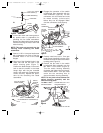

NOTE: Slightly loosen the four screws
securing the lower ring brackets to the
switch housing assembly.
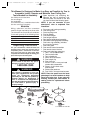
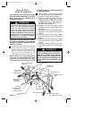
9. Securely grasp one of the lower ring
posts and raise the lower ring up to one
of the lower ring brackets. Secure the
lower ring post to the lower ring brack-
et using a bracket mounting screw
(Figure 16). Grasp the opposite post
and secure the post to the opposite
bracket using a bracket mounting
screw.
10. Secure the remaining two lower ring
posts to the lower ring brackets using
bracket mounting screws.
NOTE: After the lower ring has been
mounted, tighten the four bracket
mounting screws securing the four
brackets to the switch housing
assembly.
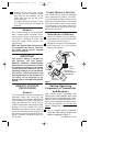
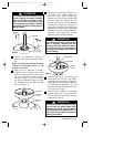
STORAGE
BRACKET
TAB
REMOTE CONTROL
TRANSMITTER
FAN/OFF
FOR/REV
LIGHT
DIMMER
HI
MED
LOW
®
Figure 17
11
Operating Your
Ceiling Fan
IMPORTANT
Fan installation must be completed,
including the installation of the fan
blades, before testing of the remote
control.
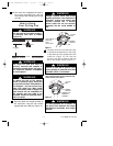
Your remote control has full control of your
fan and light.
1. Restore electrical power to the outlet
box by turning the electricity on at the
service panel.
2. To set the desired fan speed, press the
HI, MED, or LOW buttons to operate
your fan on high, medium, or low speed
(Figure 18).
3. To turn your fan off, press the FAN/OFF
button.
4. To change the airflow direction of the
fan blades, press the FOR/REV button.
The direction the fan blades turn will
change each time the FOR/REV button
is pressed.
5. To set the level of light brightness,
press and hold the LIGHT DIMMER
button. The light brightness will contin-
ue to increase then decrease while the
button is held down. When the light is
at the desired brightness, release the
button.
6. To turn the light ON and OFF, press
and release the LIGHT DIMMER but-
ton. The light will turn ON at the light
level previously set (see step 5).
Red light should turn on when any but-
ton is pressed. If the light does not
come on, replace the battery.
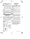
Installation of
Storage Bracket
A storage bracket is supplied with the
remote control for holding the transmitter
when not in use. If you desire to use the
bracket, use the two screws (supplied)
and install it on a wall that is away from
excess heat or humidity. When installing,
orient the bracket so that the tab is at the
top and away from the wall (Figure 17).
U.L. Model No.: CF100
BP7355 PERISTYLE CF100 9/19/07 11:26 AM Page 11