8 Installation
2.2.1 Flow Through and Insertion Mounting
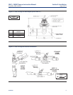
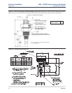
396P and 396PVP Sensors have a 1-inch MNPT process connection at the front of the sensor for
mounting into a 1-1/2 inch tee or the process pipes. See Figure 2-2 through Figure 2-7 for instal-
lation configurations.
NOTE: LARGE PIPE WRENCHES MUST NOT BE USED TO TIGHTEN THE SENSOR INTO A FLANGE OR
OTHER TYPE OF MOUNTING.
2.2.2 Submersion Mounting
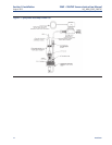
396P and 396PVP Sensors also have a 1 inch MNPT process connection at the back of the sensor.
Utilizing a standard 1 inch union, the sensor may be mounted to a 1 inch SCH 80 CPVC or PVDF
standpipe. Tapered pipe threads in plastic tend to loosen after installation. It is therefore recom-
mended that Teflon1 tape be used on the threads and that the tightness of the connection be
checked frequently to assure that no loosening has occurred. To prevent rain water or condensa-
tion from running into the sensor, a weatherproof junction box is recommended. The sensor
cable must be run through a protective conduit for isolation from electrical interference or phys-
ical abuse from the process. The sensor should be installed within 80° of vertical, with the elec-
trode facing down. The sensor’s cable should not be run with power or control wiring.
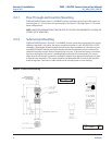
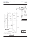
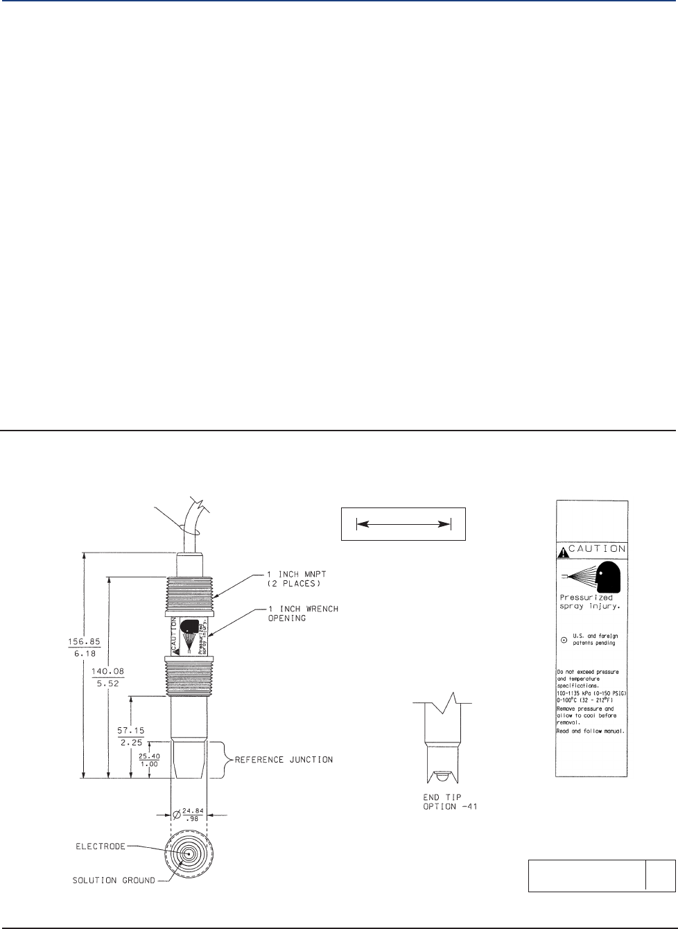
Figure 2-1. Dimensional Drawing
40396P01 D
Section 2: Installation 396P + 396PVP Sensors Instruction Manual
August 2013 LIQ_MAN_396P_396PVP


