


Wiring 13
Section 3: Wiring
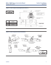
3.1 General
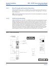
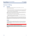
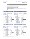
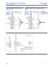
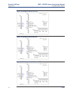
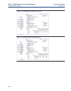
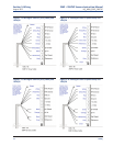
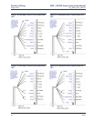
Figures in this section provide the guidelines for wiring the 396P-01 sensor to various
Analyzer/Transmitter instruments.
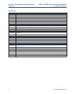
To determine which wiring guideline to use, locate the model number of the sensor to be installed.
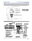
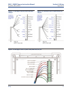
1. If the cable needs to be extended, use a high quality eleven conductor double shielded instru-
ment cable available from Rosemount Analytical. Refer to Table 3-1 for the appropriate junc-
tion box to use and the corresponding wiring details.
NOTE: If the cable is too long, loop up the excess cable. If the cable has to be shortened, cut and
terminate each conductor neatly and make sure that the overall (outermost) drain wire is not
shorted out with either of the two inner drain wires (shields).
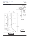
2. Signal cable should be run in a dedicated conduit (preferably an earth grounded metallic
conduit) and should be kept away from AC power lines. For your convenience, a wire nut kit is
furnished (in a plastic bag wrapped around the cable).
NOTE: For maximum EMI/RFI protection when wiring from the sensor to the junction box, the
outer braid of the sensor should be connected to the outer braided shield of the extension cable.
The outer braid of the extension cable to the instrument must be terminated at earth ground or
by using an appropriate metal cable gland fitting that provides a secure connection to the instru-
ment cable.
Wiring
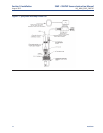
The 396P and 396PVP has an optional built-in preamplifier and is offered with a shielded cable.
The cable should be handled carefully and kept dry and free of corrosive chemicals at all times.
Extreme care should be used to prevent it from being twisted, damaged or scraped by rough,
sharp edges or surfaces.
NOTE: Remove electrical tape or shrink sleeve from gray reference wire before connecting wire
to terminal.
DANGER
DO NOT CONNECT SENSOR CABLE TO POWER LINES. SERIOUS INJURY MAY RESULT.
396P + 396PVP Sensors Instruction Manual Section 3: Wiring
LIQ_MAN_396P_396PVP August 2013