


Wall-Mounted RH Sensor and RH/Temperature Sensor
Product Information Sheet
203-5751
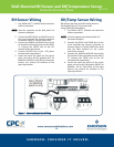
RH Sensor Wiring
1. Use Belden #8771 shielded three-conductor
cable or equivalent.
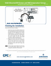
NOTE: Seat the connector on the back plate if it
becomes dislodged.
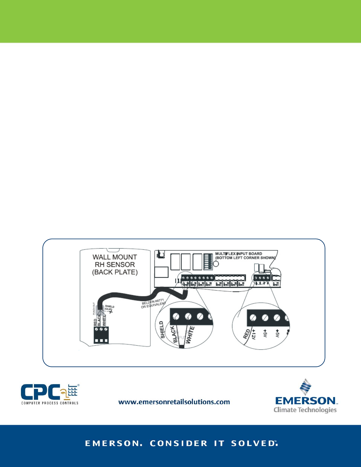
2. Connect the RED, BLACK, and WHITE wires to
the screw terminals the sensor’s connector
as shown in Figure 2. Clip the SHIELD wire.
3. Connect the SHIELD and BLACK wires to the
0V terminal of the input board (under INPUT
1). Connect the WHITE wire to the SIG
terminal of the input board.
4. Connect the RED wire to the +12V power
terminal on the input board.
5. Locate the input dip switch for the sensor
point, and set to the OFF position (LEFT for
MultiFlex, DOWN for 16AI). Refer to the input
board’s user manual for locations of the
input dip switches.
RH/Temp Sensor Wiring
RH wiring is the same as the RH wiring shown in
the diagram(Figure 2). For temp sensor
wiring, follow the steps below:
1. Use Belden #8761 shielded two-conductor
cable or equivalent.
NOTE: Seat the connector on the back plate if it
becomes dislodged.
2. Connect the BLACK and CLEAR wires to the
screw terminals the sensor’s connector as
shown in Figure 2. Clip the SHIELD wire. Note
that the third terminal on the sensor
connector is unused.
3. Connect the SHIELD and BLACK wires to the
0V terminal of the input board (under INPUT
2). Connect the CLEAR wire to the SIG
terminal of the input board.
4. Locate the input dip switch for the sensor
point, and set to the ON position (RIGHT for
MultiFlex, UP for 16AI). Refer to the input
board’s user manual for locations of the
input dip switches.
Figure 2 – Sensor and Input Board Wiring
30