


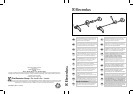

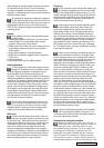


ENGLISH - 6
Safety guard extension (exclusively for use
with nylon string head)
The string cutting blade housed in the plas-
tic shield will cut the nylon string to opti-
mum length; a string that is too long reduces the
rotation speed of the engine and interferes with
cutting efficiency, as well as increasing the risk of
injury.
The extension (B) should be installed only for use
with the nylon string head, with the aid of the
string cutter blade (L), that regulates the length of
the string and thus the cutting diameter. For cor-
rect assembly see the illustration on the cover
and perform the following sequence of steps:
Insert the extension (B) on the safety guard (A) at
the reference notches (C), and fasten with the
screws (D), then apply the string cutter blade (L)
and fasten it with the screw (E) (Make sure the
screws are tightened all the way (E) and are not
loosened by the vibrations. If necessary, tighten
them again).
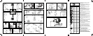
E5. Assembly/disassembly of line cutter head
Apply the nylon string head as shown in the illus-
tration: 1) Protection flange 2) Upper plate 3)
Protection (nylon string head B) 4) Nylon string
head. Tighten by turning counterclockwise. As
you tighten, hold the nylon string head and plate
still and insert the wrench or screwdriver supplied
in the holes in the plate and gearbox; first turn the
plate until the two holes match.
E6. Assembly/disassembly of grass cutter
blade
Do not use the nylon string head guard
extension (H) with metal blades.
Assemble blade as illustrated: a) Flange guard -
b) Upper cap with blade centering - c) Blade with
text and directional arrow facing upwards - d)
Lower washer - e) Fixed mower gauge - f) Blade
locking screw (length mm 16).
If you want to assemble the rotating mower
gauge,proceed as illustrated: a) Flange guard - b)
Upper cap with blade centering - c) Blade with
text and directional arrow facing upwards - d)
Lower washer - e) Spacer - f) Rotating mower
gauge - g) Blade locking screw (length mm 34,5).
Assembly of sawtooth blade and blade guard
When using the sawtooth blade, remove the
guard for the line cutter head and grass cut-
ting blade and replace the flange guard (A) with
the sawtooth blade guard (H).
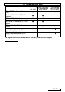
Saw tooth blades (24 - 80 tooth) have a
central base diametre of 20mm and there-
fore require the use of the appropriate size top
flange to ensure a correct fit. The part number is
detailed in the cutting attachment summary chart.
For assembly see figures (E7, E8).
2 3 4 10
2 3 4 10
2 3 4 10
F. Starting and stopping the engine
CAUTION! Start the brush cutter in a flat
place. During startup stand in a stable
position. Make sure the blade or nylon string
head do not touch the ground or any obstacles.
CAUTION! Grip the knob of the starter with
one hand and hold the machine in a stable
position with the other. (Take care not to wind the
starter string around your hand) and pull slowly
until you encounter some resistance, then pull the
cord sharply and forcefully (to start the engine
when Do not pull the starter cord all the way and
do not release it abruptly against the machine as
this could damage it.
Startup of cold engine
F1. Stop switch (A) turned to "I" opposite the
"STOP" mark.
F2. Turn the fuel enrichment lever (B) to the
closed position.
F3. Press the air purge diaphragm repeatedly until
fuel begins to fill the diaphragm (C). The
diaphragm need not be completely filled. Push
the decompression valve (D) down if your models
is fitted with one. Pull the cord until the engine
starts. Let the motor run for a few seconds and
accelerate. This will automatically return the fuel
enrichment lever to its original position.
The cutting devices are now rotating.
Startup of warm engine
F1. STOP switch turned to "I" (START). Throttle
trigger lever in minimum position (released).
Enrichment lever (B) in original position.
F3. Repeat item F3 in the previous paragraph.
Stopping the engine
F5. Turn the stop switch to "O" (STOP).
1 5 6 7 8 9 10 11 12 14