


15
ENGLAND
B
A
C
E
D2
D
D3
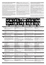
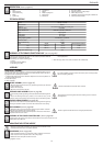
DESCRIPTION (starts at page 85)
1 Seat 6 Throttle lever 11 Gear lever (MEC)
2 Steering wheel 7 Battery 12 Agjusting levers for cutting height
3 Grass catcher bag 8 Blade coupling lever 13 Motor safety housing
4 Blade 9 Brake pedal 14 Pilot light for check-in and for full grass collection bin
5 Ignition key 10 Brake lever 15 Advance pedal (HYDRO)
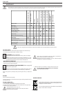
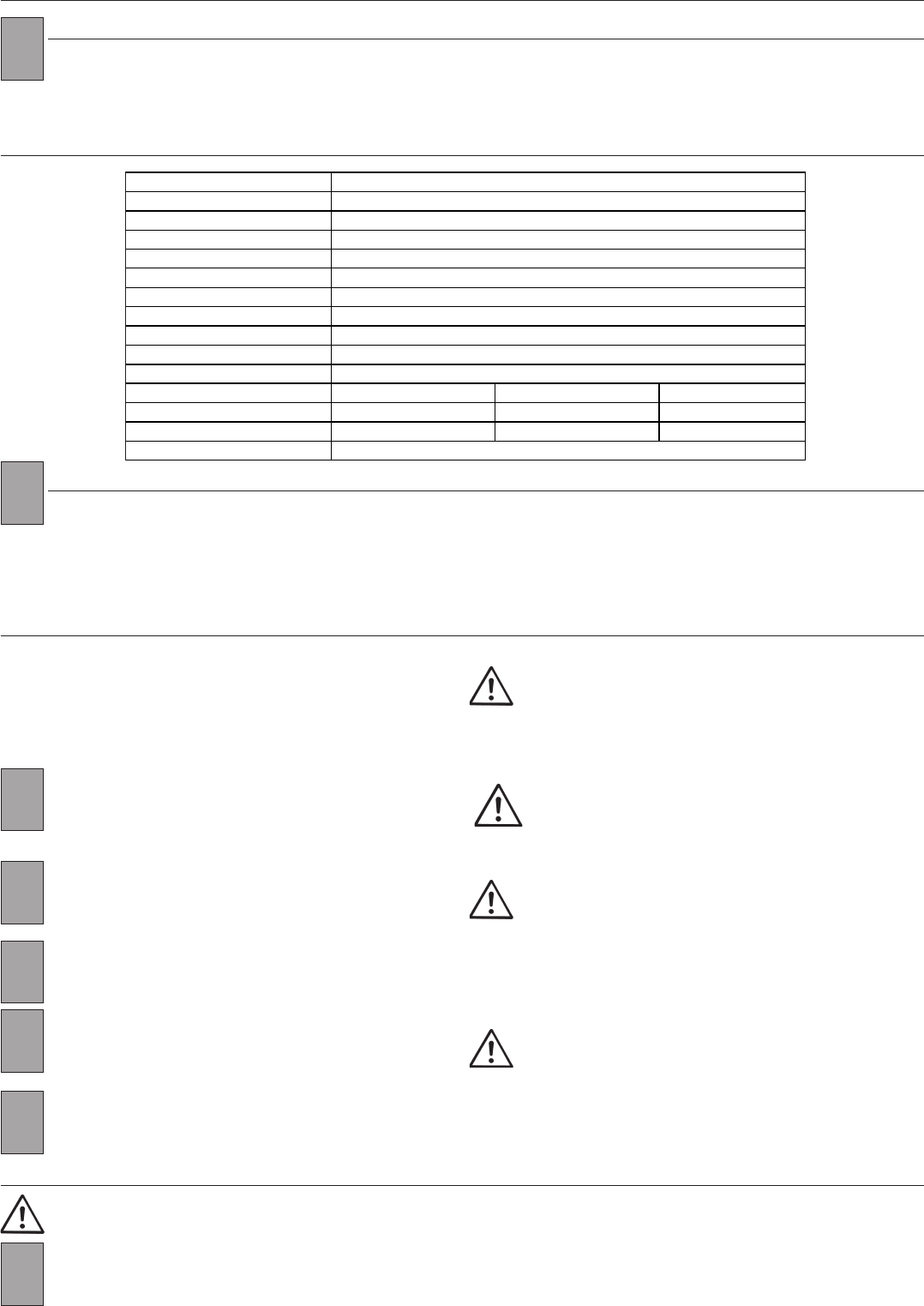
TECHNICAL DETAILS
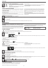
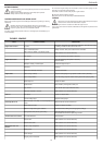
ASSEMBLY OF THE GRASS COLLECTION SACK (starts at page 85)
The grass collection bag is included with all ride-on lawnmowers as a standard
If the bag comes with the product then it not an accessory therefore delete the
word accessory and replace with part.
For assembly, you need the following parts:
- 1 Frame
- 2 Hexagonal screws (M6x16)
- 3 self-locking nuts (M5)
- 1 Fabric bag with clips
- 2 Z-shaped plates
1. Allow the bag to slide on the frame and secure with suitable clips.
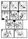
ASSEMBLY
It is strictly forbidden to start the ride-on lawnmower (even for trial purposes)
without completing assembly.
UNPACKING/ ASSEMBLY
The ride-on lawnmower is packed in a carton and is ready assembled apart from the
steering wheel, seat, grass collection bag and front wheels. Please observe the follow-
ing sequence when unpacking the machine:
1. Unpack all the parts that have been delivered. Dispose of the carton and pallet in an
environmentally friendly way.
2. Check all the parts
3. Begin assembly.
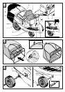
1. Mount the front wheels on the pins (15), positioning a washer (16), the wheel
(17) and a washer (18).
2. Secure with a stop (19).
3. Mount the rear wheels on the pins.
Attention: Assemble the wheel with valve outwards.
WHEEL ASSEMBLY (starts at page 85)
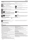
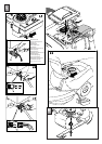
STEERING WHEEL ASSEMBLY (starts at page 86)
1. Fix the steering wheel (2) pushing until it is connected with the steering column
(20).
2. Secure the steering wheel (2) by means of the socket pin (21); put the
socket pin through the openings (on the steering column and steering wheel)
The openings at the steering wheel and at the steering column must be in
exact alignment.
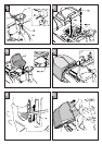
SEAT ASSEMBLY (starts at page 86)
1. Fasten the seat (1) to the support plate (22) through the 4 M8 x 18 screws.
Assemble with 4 washers Ø 9 x 24 and 4 grower.
2. Before tightening the screws, adjust the position of the seat on the holes of
the plate to suit the user's needs.
Check at regular intervals that the nuts are tightly screwed down.
ASSEMBLY OF THE GRASS COLLECTION BAG (starts at page 86)
Fasten the bin to the rear part of the ride-on-mower with the 2 H.H. 6x16, 2 screws, the 2 Z-
shaped plates and 2 M5 nuts.
ADJUSTING THE CUTTING HEIGHT
ADJUSTMENT (starts at page 86)
1. Push the adjustment lever (12) outwards in order to release it from its seat.
2. Push the lever into the required notch for the cutting height.
3. Release the lever slowly till it sticks in the notch.
The cutting height is now set.
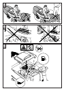
Before the cutting height is adjusted, the engine must be switched off and
the blades must have come to complete standstill.
D1
ENGINE GUARD ASSEMBLY (see page 86)
Insert the two rear ends into the special slots in the casing and fix the guard by
inserting the washers and M5 nuts on M5 x 20 screws and fix to the casing.
Engine 8,5 Hp
÷
12,5 Hp
Electric starter Electric
Advance Five forward gears and one reverse gear.
Maximum speed 9,0 Km/h
Grass collection bin 2000 mm x 820 mm x 1020 mm
Body Polypropylene
Cutting plate Sheet steel
Cutting width 67 - 76 cm
Cutting height regulation Centralised on 5 positions
Curvature radius 1,5 m
Grass collection bag 150 litre
Ty re s
Height Width
Recommended pressure
front 265 mm 85 mm 1,5 bar
rear 360 mm 120 mm 2 bar
Weight with collection bag 145