


Page 10
EZ Trim Mower Owners Manual
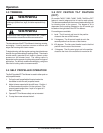
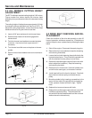
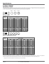
The EZ Trim Mower standard cutting height is 2-3/4 inches.
Figure number five, below, depicts the trimmer head
assembly when purchased and set at the standard cutting
height.
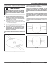
The cutting height will adjust down approximately 3/4 inch
by turning the trimmer head disk over, see Fig. # 6 & 7). To
adjust the cutting height down, remove the trimmer head
weldment before turning the trimmer head disk.
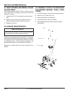
1. Insert a 9/16” open end wrench into trimmer frame.
2. Rotate trimmer head until wrench engages with
trimmer shaft.
3. Twist the trimmer head weldment counterclockwise
to remove. Use channel lock or pipe wrench if
necessary.
4. Turn trimmer head disk over and replace on trimmer
spindle.
5. Return trimmer head weldment and turn clockwise to
tighten.
4.4 ALL MODELS CUTTING HEIGHT
ADJUSTMENT
Service and Maintenance
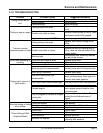
Check the condition of the drive belt annually or after 30
hours of operation, whichever comes first. If the belts are
cracked, frayed, or worn, replace them by following the steps
below.
1. Shut off the engine. Disconnect the spark plug wire.
2. Remove the front cover weldment (requires loosening
and removing three bolts).
3. Loosen the four bolts fastening the spindle hub to the
trimmer bottom frame. This will allow the spindle hub
with the attached trimmer pulley to move freely.
4. Remove the handle support channel (back cover with
tabs to adjust the handlebar). Requires loosening
and removing four bolts.
5. Remove worn or broken belt. If the belt is badly worn
and will not be used again, cut for ease of removal.
6. Install new belt from the front to the back. Feed belt
above the front trimmer pulley and below the rear
pulley.
7. Move the spindle hub by inserting a screwdriver in the
slot on the rear side of the spindle hub and applying
70 lbs. pressure forward until belt is tight. Tighten
bolts.
8. Replace front cover and secure with bolts.
9. Replace the handle support channel (back cover with
handlebar adjustment tabs). The bolts should be
secured with the bolt head beneath and the nuts and
washer above the trimmer body.
4.5 DRIVE BELT CHECKING AND RE-
PLACEMENT
Fig. #7
9/16" WRENCH
TRIMMER DISC
TRIMMER HEAD
OPTIONAL
BEAVER BLADE
Fig. #5
Fig. #6