


Grass Trimmer/Brush CuTTer
OperaTOr's manual
13
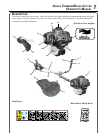
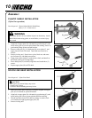
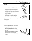
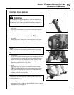
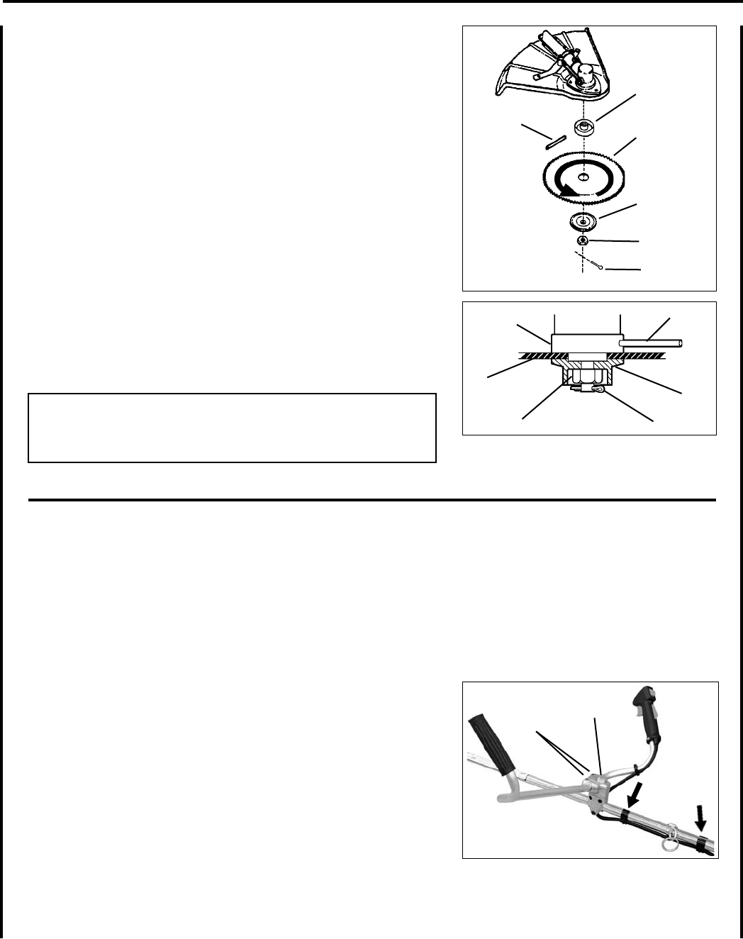
Install Blade
Parts Required: Upper Plate w/ 20 mm pilot, Lower Plate, 10 mm Nut
w/L.H. threads, 2 x 25 mm Cotter Pin, Blade.
1. Install upper plate (D) on splined PTO shaft, pilot side down.
Blade installation requires Upper Plate (D) with 20 mm pilot.
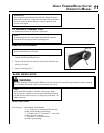
2. Install Blade (K) on upper plate pilot. Blades must be installed so
that rotation arrow on blade matches rotation of unit: teeth toward
direction of rotation (See debris shield decal). Secure blade with
Lower Plate (H), and 10 mm L.H. nut (G). Turn nut counter-clock-
wise on PTO shaft to tighten.
3. Align hole in upper plate with notch in gear housing, and insert
Locking Tool (L) to prevent splined shaft from turning. Arrow on
gear housing points to notch. Tighten 10 mm nut securely.
4. Insert Cotter Pin (F) in hole in PTO shaft, and bend pin legs around
shaft counterclockwise to retain 10 mm nut.
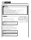
IMPORTANT
Never reuse a cotter pin - install a new cotter pin each time a blade
is installed or replaced.
5. Remove locking tool.
D
20
L
K
G
F
H
D
K
H
G
F
L
A
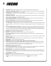
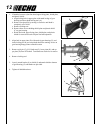
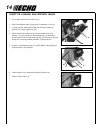
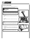
u-handle InstallatIon
Parts Required: U-Handle, Clamp w/screws, 8 mm x 55 mm hex
bolt, 8 mm at washer
1. Install upper U-Handle and bracket on lower bracket with one
(1) 8mm x 55mm bolt (A) and (1) large circular washer. Do not
tighten bolt securely until nal adjustments are completed.
2. Loosen upper (2) U-handle clamp screws (B), and position U-
handle as shown.
3. Lightly tighten 8mm bolt (A) and clamp screws (B) to hold U-
handle in position until nal adjustments are completed.
4. Route throttle linkage and ignition lead assembly along shaft and
clip as shown.
B