


12
A
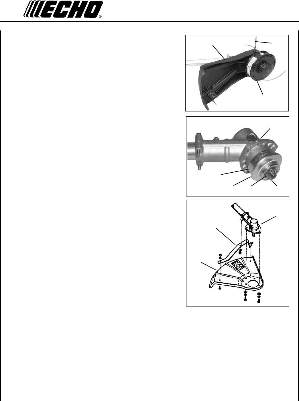
C
B
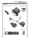
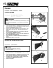
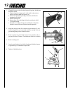
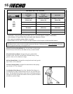
1. If installed, remove nylon line head, upper xing plate, shield plate,
and plastic shield:
a. Align locking hole in upper plate with notch in edge of gear
housing and insert head locking tool (A).
b. Remove line head (B) by turning it clockwise until head is
completely off of shaft.
c. Remove locking tool.
d. Remove three screws holding shield plate and plastic shield
(C) to gear housing.
e. Retain line head, upper xing plate, shield plate, and plastic
shield for conversion back to nylon line head operation.
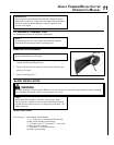
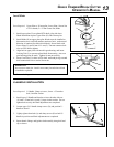
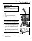
2. Align hole in upper plate (D) with notch in gear housing (E), and
insert locking tool to prevent splined shaft from turning. Arrow on
gear housing ange points to notch location.
3. Remove split pin (F), L.H. blade nut (G), lower plate (H), and up-
per plate (D) from PTO shaft. Turn blade nut clockwise to remove.
4. Remove locking tool.
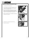
5. Loosely attach bracket (I) to shield (J) and attach shield to bottom
of gear housing (E) with hardware provided.
6. Tighten all shield hardware.
J
I
E
H
G
F
D
E