


GRASS TRIMMER/BRUSH CUTTER
OPERATOR'S MANUAL
11
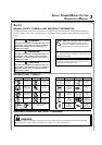
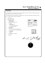
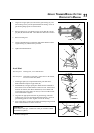
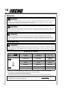
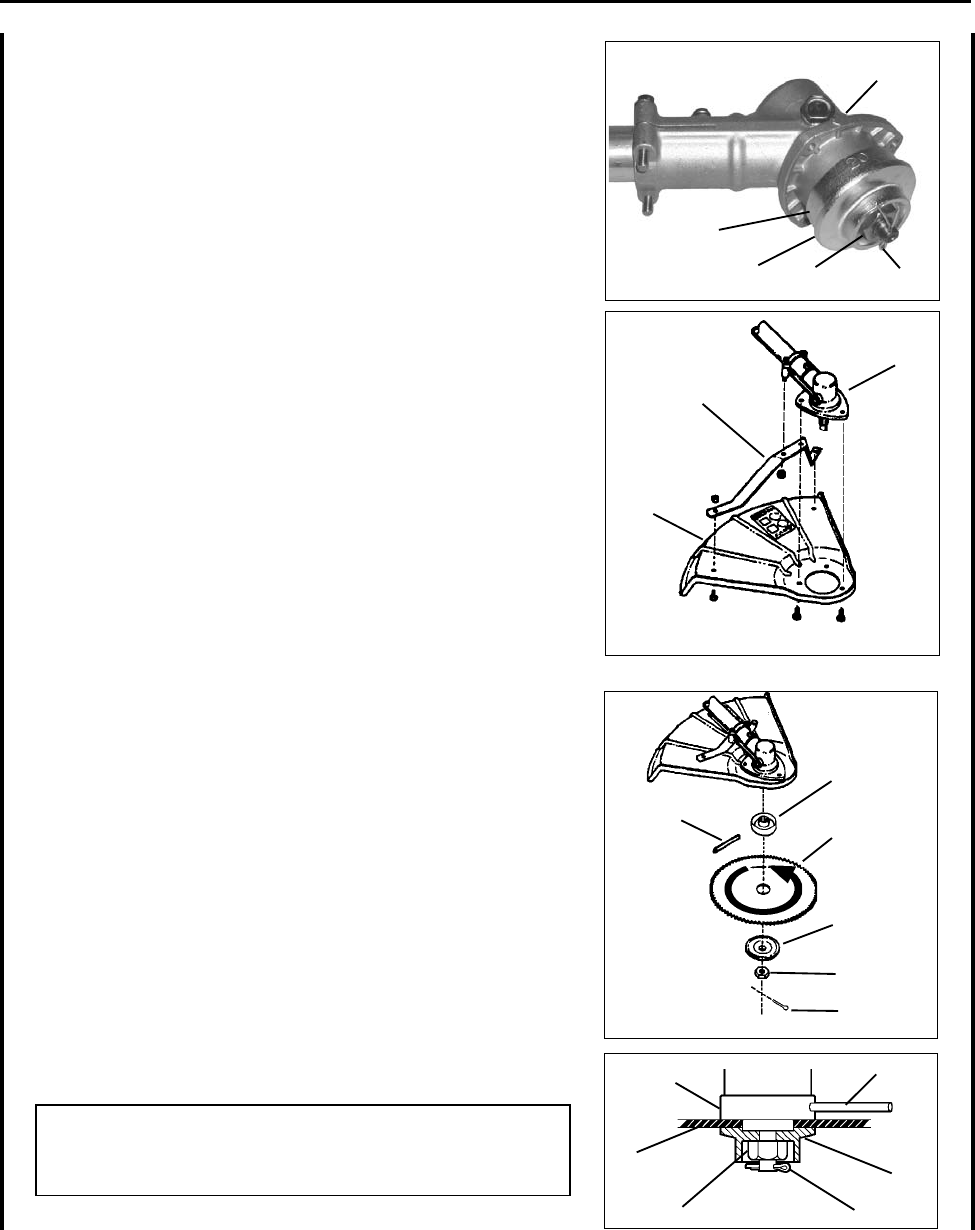
1. Align hole in upper plate (D) with notch in gear housing (E), and
insert locking tool to prevent splined shaft from turning. Arrow on
gear housing fl ange points to notch location.
2. Remove split pin (F), L.H. blade nut (G), lower plate (H), and up-
per plate (D) from PTO shaft. Turn blade nut clockwise to remove.
3. Remove locking tool.
4. Loosely attach bracket (I) to shield (J) and attach shield to bottom
of gear housing (E) with hardware provided.
5. Tighten all shield hardware.
J
I
E
H
G
F
D
E
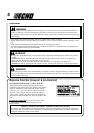
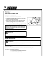
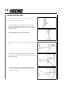
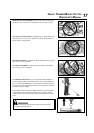
Install Blade
Tools Required: Locking Tool, 17x19 mm Wrench.
Parts Required: Upper Plat, Lower Plate, 10 mm Nut w/L.H. threads,
2 x 25 mm Cotter Pin, Blade.
1. Install upper plate (D) on splined PTO shaft, pilot side down.
Blade installation requires Upper Plate (D).
2. Install Blade (K) on upper plate pilot. Blades must be installed so
that rotation arrow on blade matches rotation of unit: teeth toward
direction of rotation (See debris shield decal). Secure blade with
Lower Plate (H), and 10 mm L.H. nut (G). Turn nut counter-clock-
wise on PTO shaft to tighten.
3. Align hole in upper plate with notch in gear housing, and insert
Locking Tool (L) to prevent splined shaft from turning. Arrow on
gear housing points to notch. Tighten 10 mm nut securely.
4. Insert Cotter Pin (F) in hole in PTO shaft, and bend pin legs around
shaft counterclockwise to retain 10 mm nut.
IMPORTANT
Never reuse a cotter pin - install a new cotter pin each time a blade
is installed or replaced.
5. Remove locking tool.
D
20
L
K
G
F
H
D
K
H
G
F
L