POWER PRUNER HEDGER ATTACHMENT
OPERATOR'S MANUAL
5
E
F
E
F
G
D
A
B
BLADE
GUARD
TOP
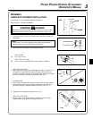
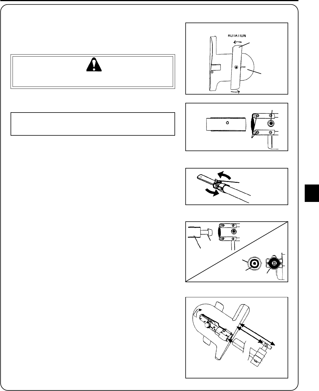
Fig. 1
ASSEMBLY
HEDGER
ATTACHMENT INSTALLATION
Tools Required: Cross Head/Flat Head Screwdriver
Parts Required: Hedger Attachment
WARNING DANGER
The Hedger Attachment blade is sharp! Always wear gloves when
handling assembly, otherwise serious personal injury may result.
1. Loosen the four (4) screws (A) and locator screw (B) on chain saw
attachment.
NOTE
Do not remove screw (B) completely from chain saw attachment,
otherwise inner lock nut will come loose and be lost.
2. Slide chain saw attachment off aluminum housing.
(PPFD-2400)
3A. Go to step five (5).
(PPT-2100, PPT-2400)
3B. Loosen center clamp knob (D) turning counter clockwise.
(PPT-2100, PPT-2400)
4. Pull aluminum housing (E) out of fiberglass housing 127mm (5 in.) or
152mm (6 in.), then slide (E) back into fiberglass housing leaving
inner drive shaft (F) exposed. Align and join star shaped drive end of
inner drive shaft (F) with hedger attachment shaft (G).
(ALL MODELS)
5. Align ridges on aluminum housing (E) with seams in hedger attach-
ment and slide onto housing. Hedger attachment guard must be
positioned properly when installed onto housing. (See Fig. 1)
6. Tighten four (4) hedger attachment screws (A).
(PPT-2100, PPT-2400)
7. Position upper drive shaft housing to desired extension length.
Tighten center clamp knob (D) turning clockwise.


