


8
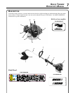
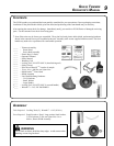
1. POWER HEAD - Factory Assembled to the Driveshaft assembly. Includes the Engine, Clutch, Fuel System, Igni-
tion System and Recoil Starter.
2. GRIP - Rear (right hand) handle.
3. STOP SWITCH - "SLIDE SWITCH" mounted on top of the Throttle Trigger Housing. Move switch FORWARD
to RUN, BACK to STOP.
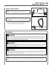
4. FRONT HANDLE - The Front (loop) handle is factory assembled to the Drive Shaft assembly but must be re-posi-
tioned for proper cutting attitude and operator comfort.
5. DRIVESHAFT ASSEMBLY - Factory Assembled to the Power Head. Includes the Rear (right hand) Handle As-
sembly, Bearing Housing Assembly, Throttle Trigger, Front (loop, left hand) Handle Assembly, Flexible Drive Cable
and Safety Decals.
6. RAPID LOADER
TM
HEAD - Contains replaceable nylon trimming lines.
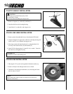
7. PLASTIC DEBRIS SHIELD ASSEMBLY - Included in plastic bag (co-pack). MUST be installed on unit before
use, see Assembly Instructions. Shield assembly includes the Cut-Off Knife. Mounts on the Gear Housing Assem-
bly just above the cutting attachment. Helps protect the operator by deecting debris produced during the trimming
operation.
8. CUT-OFF KNIFE - Trims line to the correct length.
9. THROTTLE TRIGGER - Spring loaded to return to idle when released. During acceleration, press trigger gradu-
ally for best operating technique.
10. TOP GUARD - Provides arm rest during operation and protects arm from hot engine.
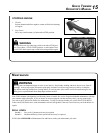
11. SPARK ARRESTOR MUFFLER OR SPARK ARRESTOR MUFFLER WITH CATALYST -The mufer or
catalytic mufer controls exhaust noise and emission. The spark arrestor screen prevents hot, glowing particles of
carbon from leaving the mufer. Keep exhaust area clear of ammable debris.
12. FUEL TANK - Contains fuel and fuel lter.
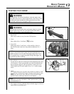
13. RECOIL STARTER HANDLE/ROPE - Pull recoil starter handle/rope using light pulling force, approximately
2/3 (2 ft.) of rope length. Two (2) to Six (6) pulls are required to properly tension starter spring prior to automatic
engine engagement. DO NOT let handle snap back or damage to unit will occur.
14. FUEL TANK CAP - Cover and seals fuel tank opening.
15. PURGE BULB - Pumping purge bulb before starting engine draws fresh fuel from the fuel tank, purging air from
the carburetor. Pump purge bulb until fuel is visible and ows freely in the clear fuel tank return line. Pump purge
bulb an additional 4 or 5 times.
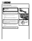
16. CHOKE - Located at the rear of the air cleaner housing. Move choke lever to "Cold Start" ( ) to close choke for
cold starting. Move choke lever to "Run" ( ) position to open choke.
17. AIR CLEANER - Contains replaceable lter element.
18. SPARK PLUG - Provides spark to ignite fuel mixture.