


10
CS-8000 TYPE1-E
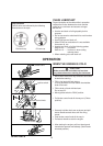
PREPARATION FOR USE
WARNING
Saw chain is sharp! Always wear gloves
when handling assembly, otherwise serious
personal injury may result.
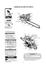
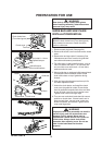
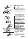
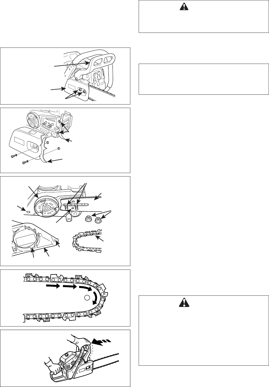
GUIDE BAR AND SAW CHAIN
INSTALLATION/REMOVAL
NOTE
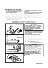
Move the chain brake lever (Front hand guard)
fully rearward to remove or install the clutch
cover to chain saw.
1. Remove spark plug lead. (See page 24)
2. Remove two clutch cover nuts and remove clutch
cover.
3. Remove bar and saw chain if necessary. See
“Maintenance and Care” section for guide bar/
saw chain maintenance procedures.
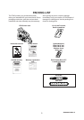
4. For initial setup, install spiked bumpers - one on
front of machine with two 6 × 14 mm bolts and
one on clutch cover with two 6 × 20 mm bolts,
washers and nuts each.
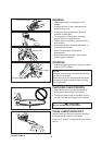
5. Mount guide bar on studs and slide toward clutch
to make saw chain installation easier. Install
chain with cutters on top of guide bar facing
forward.
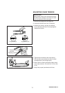
6. Slide bar forward and ensure tensioner pin fits
into lower adjustment hole.
7. Unlock the chain brake, and install the clutch
cover over the guide bar studs. Ensure brake
band is positioned around clutch drum and hole
at rear of clutch cover fits pin on engine cover.
Tighten clutch cover nuts finger tight.
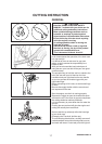
8. Turn saw over and check brake band for correct
position on clutch drum. If brake band is not in
place around drum, remove cover, make sure
brake is unlocked, and reinstall. Tighten clutch
cover nuts finger tight.
WARNING
Improper clutch cover assembly can result in
serious injury, and will cause severe saw
damage if unit is started. Never start or
operate saw if brake band is not in place on
clutch drum. Always check chain brake
operation after replacing cover. Do not use
saw if chain brake does not function
properly.
Two bolts 6 × 14 mm
Spiked bumper
Clutch cover
Chain brake lever
(Front hand guard)
Two nuts
Guide bar
Clutch
Adjustment hole
Chain
Clutch cover
Nuts
Unlock chain brake
Brake band
Nuts
Two bolts 6 × 20 mm and washers
Spiked bumper
Guide bar studs
Pin
Hole