


Page 8
MODEL W2265 ONLY
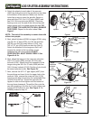
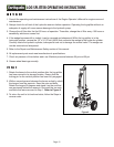
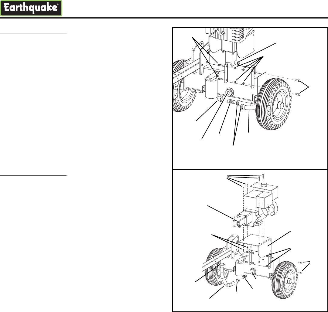
8. Remove the 90 degree street elbow (4122) and the
1” barbed coupler (4160) and insert the street
elbow first into the suction screen (4307) that has
already been assembled into the reservoir. Tighten
the elbow until it faces to the right or engine side of
the log splitter when looking at the log splitter from
the front. Then insert the 1” barbed coupler into the
street elbow and tighten. See Figure 4.
9. Assemble the pre-assembled engine assembly onto
the reservoir as shown using four 3/8-16 x 1” bolts
(2102) and four 3/8-16 bi-way locknuts (2104).
Attach the suction hose (4327) between the 1”
barbed coupler and the hydraulic pump (4344)
using two hose clamps (4169). See Figure 4. Go to
Step 12.
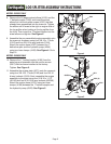
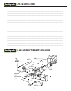
MODEL W2808 ONLY
10. Remove the 1” barbed coupler (4160) from the
parts bag and assemble into the suction screen
(4307) that has been installed at the factory.
Tighten. See Figure 5.
11. Assemble the engine plate (4371) onto the reservoir
using four 3/8-16 x 1” bolts (2102) and four 3/8-16
bi-way locknuts (2104). Next, assemble the engine
assembly to the plate using four 5/16-18 x 1-1/2”
(48156) and four 5/18-18 bi-way locknuts (60G56).
Attach the suction hose (4372) using two hose
clamps (4169) between the 1” barbed coupler and
the hydraulic pump (4323). See Figure 5.
LOG SPLITTER ASSEMBLY INSTRUCTIONS
Figure 4
Figure 5
4122
4160
4327
2102
2104
4307
4169
2102
4344
48156
4323
60G56
2102
4371
4372
4169
4169
4160
4307
2104 (4)