


13
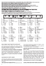
STANDARDS OF USE
NOTE – The machine can be supplied with some of the
components already fitted.
To mount the stone-guard (1), the left end of the pin
(2) must be pushed through and then inserted in the hole of
the left-hand (3) on the chassis. Line up the other end of the
pin with the relative hole in the right-hand support (4).
Using a screwdriver, push the pin into the hole so that the
groove (5) can be reached. Fit the snap ring (6) into the
groove and hook on the right (7) and left (8) springs, as
shown.
Handle type “A” - without height adjustment -
Attach the lower part of the handle (1) to the side supports
on the chassis. Secure it using the screws (2) supplied,
making sure that the centring washers (3) are positioned
correctly. Attach the upper part (4) using the screws (5)
supplied, ensuring that the spiral (6) of the starter cable is
in the correct position. Attach the control cables using the
clips (7).
Handle type “B” - with height adjustment - Return
the lower part of the pre-fitted handle (1) to its working
position and lock into place using the lower knobs (2).
Attach the upper part (3) using the screws (4) supplied,
ensuring that the spiral (5) of the starter cable is in the cor-
rect position. Attach the control cables using the clips (6).
By loosening the knobs (2) the handle can be set at three
different heights.
Assemble the dashboard (1) following the steps
shown.
For a rigid grass-catcher, assemble the two parts
(1) and (2), making sure that the hooks are fully clicked into
position.
For a cloth grass-catcher, insert the frame (11)
into the sack (12) and attach the plastic bars (13) using a
screwdriver, as shown in the drawing.
On models with an electric starter, connect the bat-
tery cable to the lawnmower’s general cable connection.
The throttle (where fitted) is controlled by the lever
(1) and positioned as shown on the relative plate.
Some models have a fixed speed, and therefore no need of
a throttle (2).
The blade brake is controlled by the lever (1), which
should be held against the handle when starting and using
the lawnmower. The engine stops when the lever is
released.
In power-driven models, draw the lever (1) towards
the handle for forward movement. The lawnmower stops
moving forward when the lever is released.
The cutting height is adjusted using the levers (1).
The four wheels must be at the same height.
MAKE THIS ADJUSTMENT ONLY WHEN THE BLADE HAS
STOPPED MOVING.
2.4
2.3
2.2
2.1
2. DESCRIPTION OF CONTROLS
1.5
1.4b
1.4a
1.3
1.2b
1.2a
1.1
1. FINISH ASSEMBLY
GB
Lift the stone-guard and attach the rigid grass-
catcher (1) or cloth grass-catcher (2) correctly as shown in
the drawings.
To start the engine, follow the instructions in the
engine booklet and then pull the blade brake lever (1)
towards the handle and give a sharp pull on the starter
cable knob (2). For models with an electric starter, turn the
starter key (3).
The lawn will look better if it is always cut to the
same height and in alternate directions.
When you have finishing mowing, release the brake
lever (1) and disconnect the spark plug cap (2). Remove the
starter key (3) (where fitted).
WAIT FOR THE BLADE TO STOP before carrying out any
type of work on the machine.
IMPORTANT – Regular, careful maintenance is essen-
tial for keeping the safety level and original perform-
ance of the machine unchanged in time.
Store the lawnmower in a dry place.
1) Wear strong working gloves during any cleaning, main-
tenance or adjustment operation on the machine.
2) Carefully clean the machines with water after each cut;
remove the grass debris and mud accumulated inside
the chassis to avoid their drying and thus making the
next start-up difficult.
3) The paintwork on the inside of the chassis may peel off
in time due to the abrasive action of the cut grass; in this
case, intervene promptly by touching up the paintwork
using a rustproof paint to prevent the formation of rust
that would lead to corrosion of the metal.
4) Should it be necessary to access the lower part, only tilt
the machine from the side shown in the engine hand-
book; following the relative instructions.
5) Do not drip petrol onto the plastic parts of the motor or
the machine to prevent damaging them and remove all
traces of spilt petrol immediately. The warranty does not
cover damage to plastic parts caused by petrol.
All operations on the blade should be carried out at
a specialized centre.
Note for specialized centres: Reassemble the blade (2) as
shown in the drawing and tighten the central screw (1)
using a torque wrench set to 35-40 Nm.
By turning the nut (1), adjust the belt’s tension to
obtain the measurement shown (6 mm).
• For models equipped with the spring, regulate the
adjuster (2) to obtain the best length of the spring (with
the clutch engaged), which is 51-52 mm.
• For models without the spring, regulate the adjuster (2) so
that the cable (3) is slightly loose, with the lever (4) at rest.
To recharge a flat battery, connect to the battery
charger (1) following the instructions in the battery mainte-
nance handbook. If the machine is to remain inactive for a
long period, disconnect the battery leads after making sure
that the battery is fully charged.
Should you have any doubts or problems, do not hesitate
to contact your nearest Service Centre or your Dealer.
4.3
4.2
4.1
4. ROUTINE MAINTENANCE
3.4
3.3
3.2
3.1
3. GRASS CUTTING