


CARE AND MAINTENANCE - MODEL 5421
DRIVE SYSTEM ADJUSTMENTS:
Adjustment of the drive system is limited to the actual function of the hydrostatic
transmissions as outlined below.
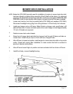
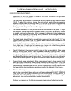
1.
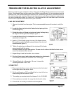
The idler pulley travel required to engage the belt drive should be held to approximately
1 3/4". To adjust this distance, loosen the nuts on both ends of the rod extending
between the idler plate and the brake shaft. Turn the rod as required to achi
eve desired
pulley travel of approximately 1 3/4" when the brake handle is released. Tighten nuts
firmly against the ball joint rod ends. See Figure 1 .
2.
The twisted idler belt (P/N 1 860) should be aligned in the center of the pulley. To adjust
the ali
gnment, tighten or loosen the nut which holds on the pulley, as required, until belt
is visually centered on the pulley. Start engine and disengage brake to determine
whether pulley alignment is maintained during operation. Shut off engine and repeat
procedure, if necessary. See Figure 2.
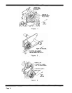
3.
The brake bands should fit tightly around brake drums with the brake handle "on", and
release drums with handle in the "off" position. Brake handle should be placed in both
"off" and "on" positions several times to det
ermine whether brake bands are functioning
correctly. If band is too loose, tighten the nut on the threaded end of eyebolt extending
from brake band. If band does not release drum, loosen nut until achieving desired
results. Repeat procedure, if necessary. See Figure 3.
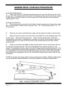
4.
Neutral Adjustment. Swing upper control levers out into the neutral slots. Raise upper
body to the fully open position. Start engine and disengage parking brake. Caution
should be used when releasing parking brake as mower may tend to cr
eep or move prior
to adjustment. If adjustment is required, loosen lock nuts at each end of the control rods
and back off the tension on each spring block. Turn control rods in or out until neutral
is obtained on each hydrostat. Re-tighten lock nuts and tension bolts on spring blocks.
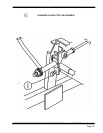
5.
Forward travel speed adjustments. Stop engine, move levers to drive position, lightly
push each upper control lever forward until a resistance is felt on the lever. At this time,
check that the forward lever stops on the b
ottom of each lever are hitting the stop blocks.
If adjustment is required, loosen the lock nuts on the lever stop and turn the bolt in until
the lever hits the stop block before resistance is felt in the hydrostat. See Figure 4.
6.
Balance of travel spee
d. If mower tends to pull to either side, readjust lever stop on fast
side to slow the hydrostat down and even out the ground speed. DO NOT SPEED UP
THE SLOW SIDE, AS OVER STROKING OF THE HYDROSTAT COULD RESULT IN
DAMAGE TO THE UNIT. If upper control levers are slightly off-
set following this
adjustment, they can be realigned by bending them slightly.
Refer to the diagrams on the following pages for the location of adjustment points.