


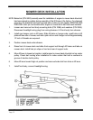
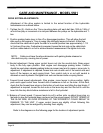

CARE AND MAINTENANCE - MODEL 5501
DRIVE SYSTEM ADJUSTMENTS:
Adjustment of the
drive system is limited to the actual function of the hydrostatic
transmissions as outlined below.
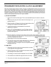
1 . Tighten the (2) J-bolts on the T-
box mounting plate until each belt has 1/8th to 1/4th of
an inch free play or movement at a mid-point between the pulleys on the hydrostats and T-
box.
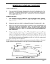
2. Position parking brake lever in the off or disengaged position. This will allow the belt
idler used on the engine to T-box to swing fully and apply tension to the belt. At this time,
check that the cable which pulls the idler to a neutral position has approximately 1 -1/2
to 2 inches of free play. If adjustment is required, loosen the lock nuts on the cable block
and turn cable sleeve in or out to achieve desired measurement. Re-tighten lock nuts.
NOTE: Cable must have the above dimension with parking brake released or
drive belt may slip, causing loss of power.
3. Neutral adjustment. Swing upper control levers out into the neutral slots. Raise upper
body to the fully open position. Start engine and disengage parkin
g brake. Caution
should be used when releasing parking brake as mower may tend to creep or move prior
to
adjustment. If adjustment is required, loosen lock nuts at each end of the control rods
and
back off the tension on each spring block. Turn control rods in or out until neutral
is
obtained on each hydrostat. Re-tighten lock nuts and tension bolts on spring blocks.
4. Forward travel speed adjustments. Stop engine, move levers to drive position, lightly
push each upper control lever forward until a resist
ance is felt on the lever. At this time,
check that the forward lever stops on the bottom of each lever are hitting the stop blocks.
If
adjustment is required, loosen the lock nuts on the lever stop and turn the bolt in until
the
lever hits the stop block before resistance is felt in the hydrostat.
5. Balance of travel speed. If mower tends to pull to either side, re-
adjust lever stop on
fast side to slow the hydrostat down and even out the ground speed. DO NOT SPEED
UP
THE SLOW SIDE, AS OVER STROKING OF THE HYDROSTAT COULD RESULT
IN
DAMAGE TO THE UNIT. If upper control levers are slightly off-
set following this
adjustment, they can be realigned by bending them slightly.
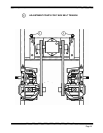
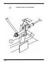
Refer to the diagrams on the following page for the location of adjustment points.
Page 18