


PDG-2515/2520 Operating Manual
Page 10
MNPDG2515-2520R0.doc
© 2004 Directed Energy, Inc.
the contrast settings of the unit. The operating modes will be discussed in
more detail in section 9.0. Enabling and disabling a channel can also
happen on the fly in pulse generation and Divide By N modes. In pulse
count mode this needs to be set before hand so the unit does not sit in an
unknown state if it has not finished it’s count set, therefore, the unit will not
allow it to be changed while pulsing. In Burst mode, disabling the channel
is not available and both are enabled. When the mode is switched from
Burst mode, the enable/disable settings will return to where they were
previous to Burst mode. The trigger can be set to internal or external in
pulse generation and pulse count modes. Note that the unit will “lock up”
until it has finished it’s pulse count in external mode so the external
triggering device must give it AT LEAST as many pulses as is entered. If
this does not occur, the device can be “released” by switching modes. The
sync can also be run off channel 1 or channel 2. This is especially useful
in Divide By N mode and pulse count mode. Not that in Burst mode, the
sync is a packet period limited by at most 95% duty cycle regardless of
this setting.
The contrast setting can also be changed in this menu. If the contrast is
adjusted by using the encoder knob or using the x10 button, a ‘?’ will
appear at the end of the setting. This means that while the unit is powered
this is the setting that the unit will retain but when powered down and
powered up again the unit will revert to the last saved contrast. By
depressing the ENTER button the contrast will be saved in non-volatile
memory and the unit will come up under this contrast setting. The contrast
is has numerous settings, and a coarse and a fine adjust. The letter is a
course adjustment and the number is the fine adjust. The course adjust is
manipulated with the x10 button and the fine adjust is set by the encoder
knob.
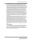
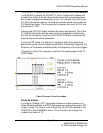
THE LOGIC MENU
The LOGIC MENU allows the user to logically AND or OR outputs OUT1
and OUT2. LOGIC1 will output on the OUT1 channel (note: the invert
function will invert the channel AFTER the logic has been applied – this is
shown in the LOGIC AND POLARITY FUNCTIONAL DIAGRAM below).
LOGIC2 will output on the OUT2 channel.