


107396
For more information, visit www.desatech.com
For more information, visit www.desatech.com
5
5
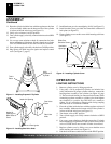
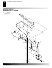
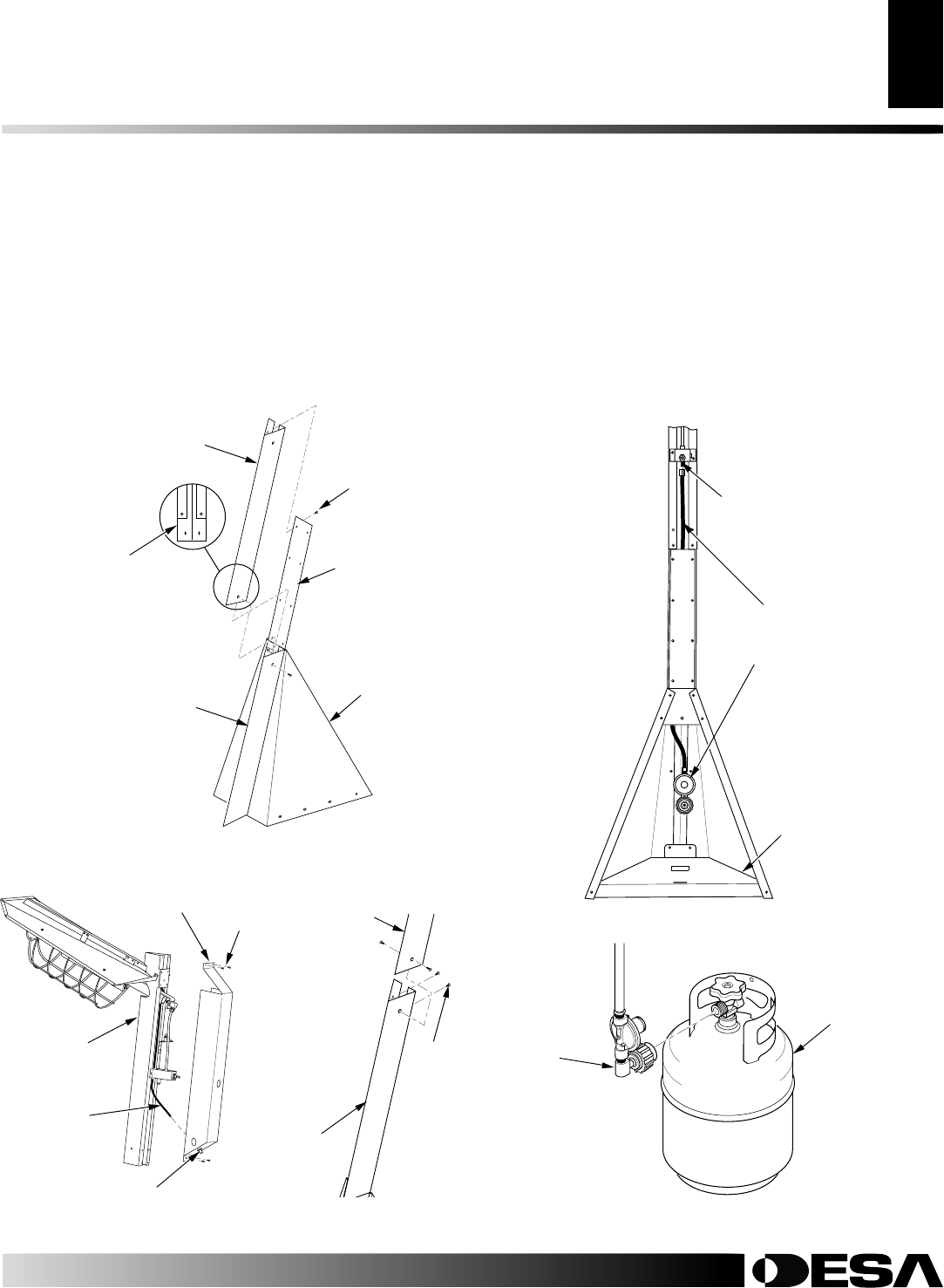
Figure 7 - Removing
Control Cover
Control Cover
Piezo Ignitor
Electrode
Wire
Upper Mast
Assembly
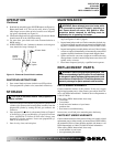
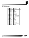
Figure 8 - Attaching Upper
Mast Assembly
Upper Mast
Assembly
Lower
Mast
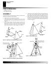
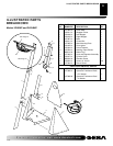
Figure 6 - Attaching Lower Mast
Base Assembly
Back
Plate
Center
Wrapper
Lower Mast
Bottom of
Lower Mast
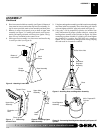
ASSEMBLY
Continued
Screw
Screw
Screw
6. Place lower mast inside base assembly (see Figure 6). Bottom of
lower mast has cut out section that slips into base assembly. Us-
ing 10 screws provided, attach to base assembly and back plate.
7. Remove 4 screws from control cover on back of upper mast
assembly (see Figure 7). Carefully pull control cover from as-
sembly and unplug electrode wire from piezo ignitor. The ig-
nitor will stay assembled to the control cover.
8. Slide upper mast assembly over lower mast and install using
4 screws provided (see Figure 8).
9. Using hose and regulator assembly provided, route hose up through
mast from inside base assembly. Screw hose fitting onto inlet of
valve and tighten with 9/16" open end wrench (see Figure 9).
10. Using only a 20 lb. propane/LP cylinder, not included (see
safety information for proper cylinder selection), connect the
hose/regulator assembly to the cylinder (see Figure 10). When
connecting regulator assembly to cylinder valve, hand tighten
nut clockwise to a positive stop. DO NOT use a wrench to
tighten. Use of a wrench may damage quick closing coupling
nuts and result in a hazardous condition.
Figure 9 - Installing Hose and Regulator Assembly
Gas Valve Inlet
Gas Hose/
Regulator
Assembly
Base
Figure 10 - Connecting Hose/Regulator Assembly to Propane/LP
Cylinder
20 lb. Propane/LP
Cylinder
Hose/Regulator
Assembly
ASSEMBLY