


Page 17
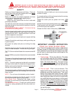
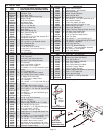
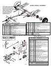
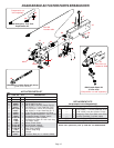
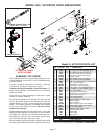
MODEL DA91 ACTUATOR PARTS BREAKDOWN
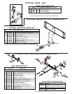
5398 Master Cylinder Repair Kit
(gasket 05681 included)
2î Lever Lock Coupler
RATED AT 6000#
not included
REF.
NO. PART NO. QTY. DESCRIPTION
Model 91 ACTUATOR PARTS LIST
1. 09417 1 6000# 2" Lever Lock Coupler (zinc plated)
2. 01896 3 1/2"-13UNC x 4" Hex Head Bolt (gr.5)
3. 02178 3 1/2"-13UNC Nylon Insert Lock Nut
4. 05426 1 Front Shock Pin (drop tube actuators)
5. 11079-95 1 Drop Tube Actuator Slider (plated)
6. SB12426 1 Damper/ Shock
7. 11164-95 1 3 Bolt Mount Outer Case (plated)
8. 05424 2 5/16" External Tooth Lock Washer
9. 02363 2 5/32" x 1 1/4 Cotter Pin(Qty 3 w/drop tube)
**10. 05408 1 3/32" Cable with hooks
11. SB10555 - Replacement S-Hooks ONLY
**12. 05693-95 1 Emergency Lever Spring (plated)
13. 05961 2 5/16"-18UNC x 5/8" Hex Head Bolt (gr.5)
14. 00618 4 1/4-20UNC x 2" Hex Head Bolt (gr.5)
15. 00057 4 1/4" Lock Washer
**16. 05951 1 Emergency Lever Assembly
17. 03876 1 Master Cylinder Cap w/ Diaphragm & O-ring
- 05849 1 O-Ring Only (not shown)
18. 05977 1 Push Rod Assembly
19. 00062 4 1/4-20 UNC Hex Nut
20. 09153 - Plastic Master Cyl. Gasket ONLY
21. 10616 1 Master Cylinder
- 11190 - Master Cylinder
22. SB12098 1 .018 Connector Orifice (Drum Brakes)
- 05679 1 Inverted Flare Adapter (Disc Brakes)
23. 03866-95 1 Lever Guide (plated)
24. 05687 1 Master Cylinder Protective Boot
25. 05986-95 1 Connecting Pin (plated)
26. 10965 1 Upper Slider
27. 10966 1 Lower Slider
28. 10967 2 Side Spacers
- 5401 - Lever Replacement Kit (incl. items w/**)
- 5650 - Master Cyl. Replacement Kit (drum)
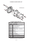
- 5495 - Coupler Repair Kit
23
**16
22
20
21
19
17
24
13
14
11
9
**10
6
4
3
2
7
5
15
1
8
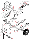
Please order replacement parts by PART NO. and DESCRIPTION
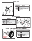
2
8
9
14
15
18
19
25
26
27
28
28
**12
9
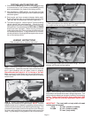
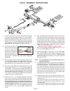
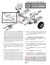
BLEEDING THE SYSTEM
The first requirement for safe, sure hydraulic braking is the use
of quality brake fluid. Use only DOT-3 or DOT-4 brake fluid from
a sealed container.
If pressure bleeding equipment is available, follow the
manufacturerís instruction in bleeding the system.
If system must be bled manually, proceed as follows: Fill
master cylinder with fluid. Install bleeder hose on first wheel
cylinder to be bled.
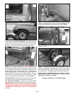
Have loose end of hose submerged in brake fluid in glass
container to observe bubbling.
By loosening the bleeder screw located in the wheel cylinder
one turn, the system is open to the atmosphere through the
passage drilled in the screw. Pump actuator with long steady
strokes. The bleeding operation is completed when bubbles
no longer rise to the surface of the fluid. Be sure to close
bleeder screw securely.
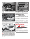
Repeat bleeding operation at each wheel cylinder. During the
bleeding process, replenish the brake fluid, so the level does
not fall below the 1/2 full level in the master cylinder reservoir.
After bleeding is complete, make sure master cylinder reser-
voir is filled and filler cap is securely in place.
After the bleeding operation has been completed, apply pres-
sure to the system and check the whole brake system for leaks.
5495
Coupler Repair Kit