


Page 19
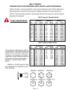
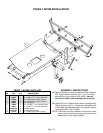
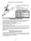
TRUSS-T BOOM INSTALLATION
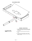
19. Begin by bolting on the Boom Mounting Plate (supplied
with Truss-T Boom) using four 3/8" x 1-1/4" hex head
bolts (#2) and nylon locknuts (#3). NOTE: Use the
hole to the inside of the mounting plate as shown.
ASSEMBLY INSTRUCTIONS
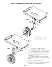
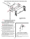
20. Attach the Truss-T Boom Center Section to the Mounting
Plates using four 5/16" x 1-1/2" square u-bolts (#6),nylon
locknuts (#4) and flatwashers (#5). (U-bolts and Locknuts
are supplied with Truss-T Boom.)
NOTE: The boom mounting brackets and the boom center
section may be mounted using any set of two holes
depending on boom height desired.
9
2
8
2
3
3
7
7
7
10
4
1
1
5
5
6
6
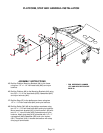
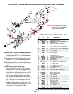
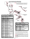
Please order replacement parts by PART NO. and DESCRIPTION.
10
TRUSS-T BOOM PARTS LIST
REF. PART
NO. NO. QTY. DESCRIPTION
1. 02678-95 4 Boom Mounting Plate
2. 00523 4 3/8"-16 UNC x 1-1/4" Hex Head Bolt
3. 02592 4 3/8"-16 UNC Nylon Insert Locknut
4. 02802 8 5/16"-18 UNC Nylon Insert Locknut
5. 00004 8 5/16" Flatwasher
6. 00909 4 5/16"-18 UNC x 1-1/4" Square U-Bolt
7. 00967 6 1/2"-13 UNC x 1-1/4" Hex Head Bolt
8. 02693-30 2 Boom Mtg. Brace
9. 01792-30 2 23" Boom Mtg. Bracket
10. 02178 6 1/2"-13 UNC Nylon Insert Locknut
4