


Dayton Operating Instructions and Parts Manual
7
Version B - For Reduction G016.J
®
Models 3WY47, 3W735B, 3W736C, 3WY44, 3TE27A,
3WY45, and 3WY46
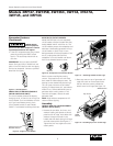
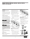
ENGINE CIRCUIT BREAKER (MODELS
3WY46 AND 3WY45 ONLY)
This circuit breaker protects the battery
charging circuit. A short circuit will trip the
circuit breaker. The circuit breaker will also
trip if you install battery wrong. Push
circuit breaker button to reset. Model
3WY47: Fuse located inside keyswitch box.
OFF
ON
START
ENGINE SW
CIRCUIT
BREAKER
ON/push OFF
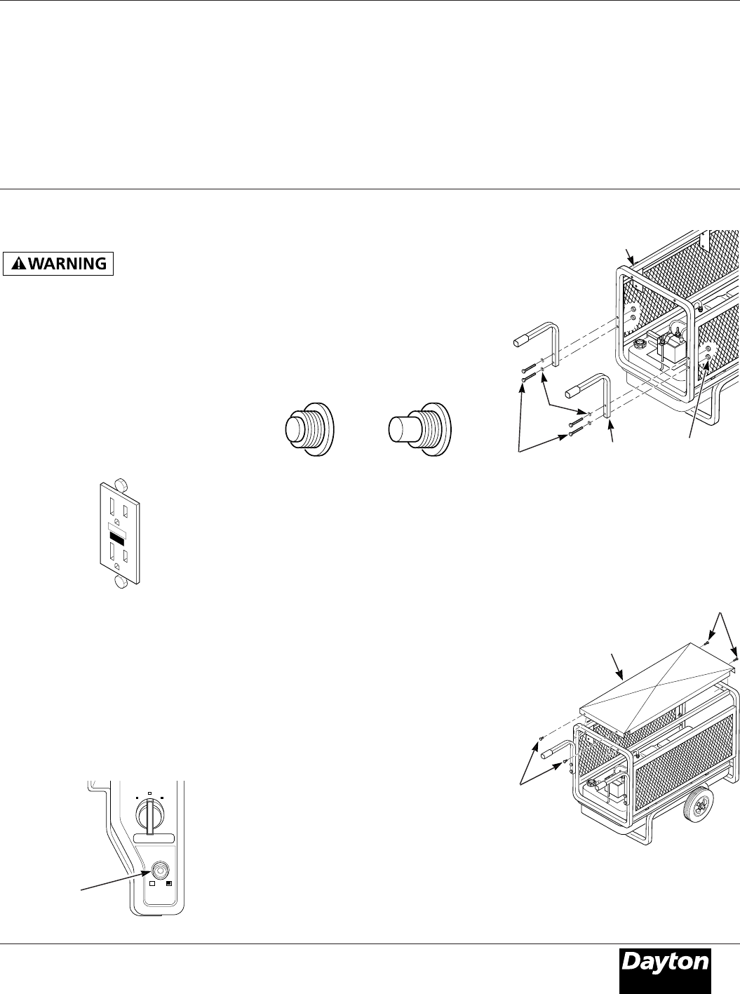
Figure 9 – Engine Circuit Breaker
Engine Circuit
Breaker Button
TrippedNormal
20
20
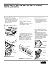
Figure 10 – Receptacle Circuit Breaker Button
RECEPTACLE CIRCUIT BREAKER
Model 3W735B has only one receptacle
circuit breaker. All other models have four,
except Model 3WY47 which has six. The
circuit breakers protect the receptacles and
alternator. Overloading generator will trip
circuit breaker. A short circuit in item
being powered will also trip breaker. If this
occurs, unplug electrical load from
receptacle. Let circuit breaker cool down.
Push circuit breaker button to reset.
Generator Features
(Continued)
Electric motors need higher starting
current. They require up to 3 to 6-times
their rated full-load wattage to start. The
starting current needed may be too high.
This can cause nuisance circuit breaker
tripping. To help prevent this, start electric
motors first. Connect additional items to
generator after starting motors. If this
continues to happen, reduce the total
generator load.
NOTE: High ambient temperatures will
cause nuisance tripping.
Assembly
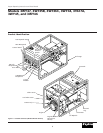
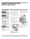
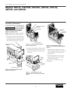
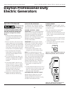
HANDLE AND TOP COVER ASSEMBLY
(MODEL 3WY47 ONLY)
1. Remove the two bolts, lock nuts, and
washers holding side panels to control
panel end of roll cage. Insert bolts with
washers through two holes in the
handle and then back through roll cage
and side screen panels (See Figure 11 ).
Tighten the lock nuts against the side
screen panels.
F
FUEL
F
F
U
E
L
2. Place top cover on top of generator roll
cage with notch on control panel side.
Use four #8 sems screws provided to
attach cover to roll cage (See Figure 12).
Figure 11 – Attaching Handles to Roll Cage
Figure 12 – Attaching Top Cover to Roll Cage
Bolts
Roll Cage
Washers
Top Cover
SEMS
Screws
SEMS Screws
Lock Nuts
Handle
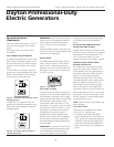
RESET
TEST
Figure 8 - GFCI Receptacle
If RESET button
does not pop out,
do not use the GFCI receptacle. Contact
a qualified electrician for repairs.
2. If the GFCI receptacle tests okay, restore
power by pushing the RESET button
back in. The test lamp should work at
this time.
IMPORTANT: You must press the RESET
button firmly and fully. It should lock into
place. If the GFCI does not lock into place,
do not use receptacle. Contact a qualified
electrician for repairs.