


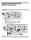
Dayton Operating Instructions and Parts Manual
15
Version B - For Reduction G016.J
®
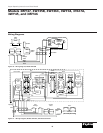
Models 3WY47, 3W735B, 3W736C, 3WY44, 3TE27A,
3WY45, and 3WY46
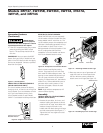
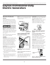
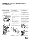
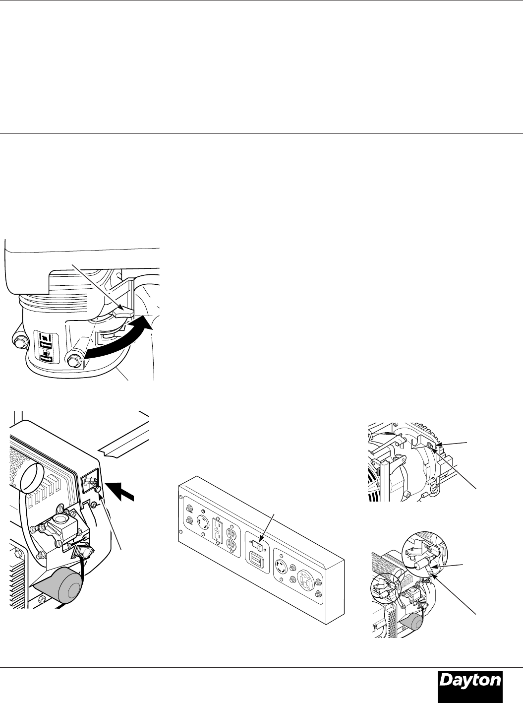
Figure 29– Choke Lever Opened
(Model 3WY47 Only)
Choke
Button
(Open
Position)
5. As engine warms up, slowly move
choke lever fully to the right (See Figure
28). This opens the choke. On Model
3WY47, the choke will automatically
open (See Figure 29).
Figure 28 – Choke Lever Opened
Choke Lever (Open Position)
Operation (Continued)
AUTO-IDLE OPERATION
IMPORTANT: Never start engine with
electrical loads connected. Start engine
before adding electrical loads.
1. If engine is cold, turn the auto-idle
switch OFF.
2. Start engine. Allow engine to warm up
with no load for five minutes.
3. Turn auto-idle switch ON. Engine will
slow to idle speed. Engine idle speed is
preset. Idle speed adjustment should
not be necessary.
4. Operate generator according to
specifications outlined in owner's
manual.
5. Engine will automatically increase to
normal operating speed when you plug
load into any generator outlet.
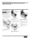
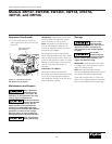
NOTE: The 250 Volt/50 Amp receptacle is
not connected through the auto-idle
circuit. The auto-idle switch must be
turned off to get full power out of this
receptacle (See Figure 30).
6. The auto-idle system should be turned
OFF when generator is shut down.
ADJUSTING THE IDLE SPEED
IMPORTANT: Adjust the idle speed only:
• If the idle speed becomes too high.
• If the engine idle speed will not
regulate (engine idles and speeds up
again and again).
1. Turn auto-idle switch OFF. Start engine.
Allow engine to warm up with no load
for five minutes.
2. Remove engine linkage cover (Models
3WY46 and 3WY45 only).
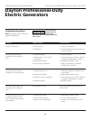
3. Push plunger into solenoid body to
manually engage solenoid and set idle
speed.
4. Loosen the M8 nut that holds the
solenoid mounting bracket to the
generator (Models 3WY46 and 3WY45
only, See Figure 31). Do not loosen bolt
that holds the solenoid mounting
bracket to the generator on Model
3WY47, See Figure 32).
Figure 30 - Auto-Idle Switch Location on
Control Panel
R
E
S
E
T
T
E
S
T
1
2
0
V
O
L
T
S
RESET
240 VOLTS
RESET
RESET
RESET
E
N
M
0
0
00
00
05
H
O
U
R
S
1
/1
0
120
ONLY
120
240V
O
F
F
EN
G
IN
E
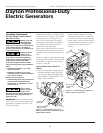
Figure 31 - Solenoid Bracket Location
(Models 3WY46 and 3WY45 Only)
Figure 32 - Solenoid Bracket Location
(Model 3WY47 Only)
Solenoid
Mounting
Bracket
M8 Nut
Solenoid
Mounting
Bracket
Bolt
Auto-Idle
Switch