


25
USING THE THREE POINT HITCH
WARNING: Always disengage the PTO,
stop the engine, and set the parking
brake before dismounting the tractor
to connect, disconnect, or adjust three
point hitch mounted implements.
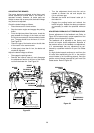
Use the rear three point hitch system to attach
three point mounted implements, which are
normally driven by the rear PTO. Using the position
control feature of the tractor’s hydraulic lift system,
the three point hitch system provides for variable
positioning of the implement as well as allowing the
implement to be fully raised for transport.
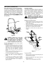
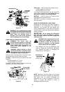
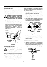
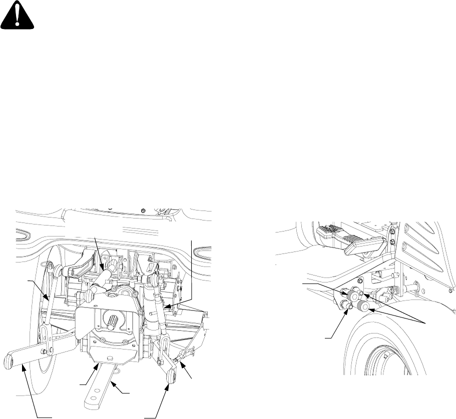
Read the ADJUSTMENTS section for instructions
on adjusting the RH adjustable lift link, upper hitch
link, and hitch chain. See Figure 22.
Figure 22
USING THE HITCH PLATE
Use only the hitch plate and drawbar (Refer to Fig-
ure 22), for towing pull-behind equipment (carts,
trailers, etc.) or dragging loads.
Raise the lower links of the three point hitch to their
highest position to prevent interference with the
towed equipment.
IMPORTANT:
When transporting pull-behind
equipment, always use a safety chain to supple-
ment the connection between the tractor and
towed equipment. The safety chain must have
a strength rating equal to or greater than the
gross weight of the equipment being towed.
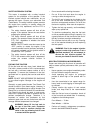
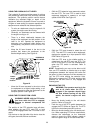
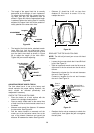
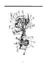
USING THE AUXILIARY HYDRAULIC VALVE
Some tractors may be equipped with an auxiliary
hydraulic valve package. This package provides
two hydraulic circuits for operating optional
equipment that can be installed on the tractor.
The male and female hydraulic couplers, located
beneath the right running board, are marked with
color coded washers that should match the color
coded hydraulic lines of
Cub Cadet
equipment. See
Figure 23.
IMPORTANT: If color coding is not present, note
that the inner hydraulic couplers represent one
hydraulic circuit and the outer couplers the
other. Do not cross connect circuits when
connecting hydraulic lines of optional
equipment.
Figure 23
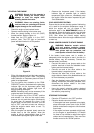
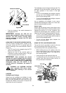
Using the Auxiliary Hydraulic Control Handle
Use the auxiliary hydraulic control handle located
on the right fender as follows:
• Pull the handle rearward to raise the front
hitch or front loader boom. See Figure 24.
• Push the handle forward to lower front hitch
or front loader boom. Refer to Figure 24.
• Push the handle fully forward until it locks in
the detent position to place the front hitch or
front loader boom in the float position.
• Push the handle to the right to angle (if
equipped) the front hitch to the right or dump
the loader bucket. Refer to Figure 24.
• Pull the handle to the left to angle (if
equipped) the front hitch to the left or roll
back the loader bucket.
FIXED
LIFT
HITCH
CHAIN
HITCH
PLATE
LOWER HITCH LINK
LINK
DRAW
BAR
ADJUSTABLE
LIFT LINK
UPPER
HITCH LINK
INNER
COUPLERS
OUTER
FEMALE
COUPLER
OUTER
MALE
COUPLER