


11
NOTE: References to LEFT, RIGHT, FRONT, and
REAR indicate that position on the tractor when
facing forward while seated in the operator’s seat.
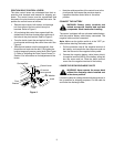
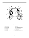
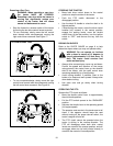
A. Deck Height Index
The deck height index consists of six index notches
located on the front/right of the seat box frame. Each
notch corresponds to a 1/2 inch change in the deck
height position ranging from 1-1/2 inches at the low-
est notch to 4 inches at the highest notch.
B. Deck Lift Handle
The deck lift handle is located on the front/right of the
seat box frame, and is used to raise and lower the
mower deck.
Pull the handle to the left out of the index notch and
push downward to lower the deck, or pull upward to
raise the deck. When the desired height is attained,
move the lift handle to the right until fully in the index
notch.
C. RH and LH Drive Control Levers
The RH and LH control levers are located to each
side of the operator’s seat. These hinged levers open
out to the side in the neutral position to permit the
operator to be seated or to leave the tractor seat. The
levers must be fully opened out in the neutral position
to start the tractor engine.
Each lever controls the respective RH or LH transmis-
sion. Consequently, these levers control all of the
movements of the tractor. Driving and steering utiliz-
ing these control levers is quite different from
conventional tractors, and will take some practice to
master. Refer to SECTION 2: OPERATION for
instructions on using the control levers.
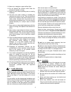
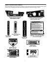
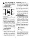
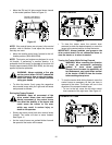
D. Ignition Switch
The ignition switch is located on the RH console to
the right of the operator’s seat.
The ignition switch has three positions as follow:
Figure 5
OFF - The engine and electrical system is turned off.
ON - The tractor electrical system is energized.
START- The starter motor will turn over the engine.
Release the key immediately when the
engine starts
NOTE: To prevent accidental starting and/or battery
discharge, remove the key from the ignition switch
when the tractor is not in use.
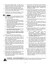
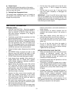
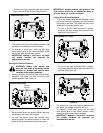
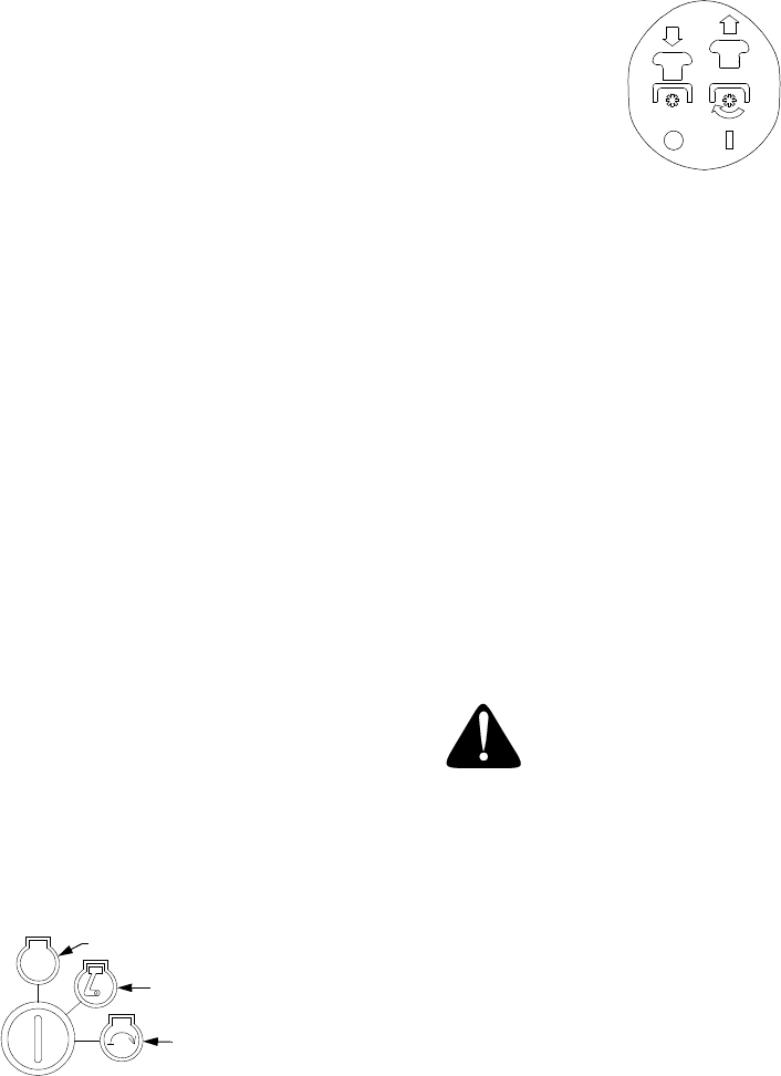
E. Power Take-Off (PTO) Switch
The PTO switch is located on the RH console to the
right of the operator’s seat.
Figure 6
The PTO switch operates the electric PTO clutch
mounted on the bottom of the engine crankshaft. Pull
the switch knob upward to engage the PTO clutch, or
push the knob downward to disengage the clutch.
The PTO switch must be in the "disengaged" position
when starting the engine.
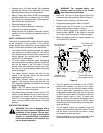
F. Transmission Bypass Rods (Not Shown)
The transmission bypass rods (one for each the RH
and LH transmission) are located beneath the frame
platform, just inside each rear wheel.
When engaged, the two rods open a bypass within the
hydrostatic transmissions, which allows the tractor to
be pushed short distances by hand. Refer to
SECTION 4: MAINTENANCE for instructions on
using the bypass feature.
WARNING: Never tow your tractor.
Towing the tractor with the rear wheels
on the ground may cause severe damage
to the transmissions.
G. Cup Holder
The cup holder is located toward the rear of the RH
console to the right of the operator’s seat.
H. Storage Tray
The storage tray is located at the rear of the RH
console.
J. Seat Adjustment Lever (Not Seen)
The seat adjustment lever is located below the front/
left of the seat. The lever allows for adjustment of the
fore to aft position of the operator’s seat. Refer to
SECTION 3: ADJUSTMENTS for instructions on
adjusting the seat position.
K. Fuel Tank Cap
The fuel tank cap is located at the rear of the LH
console. Turn the cap counterclockwise to unscrew
and remove from the fuel tank. Always re-install the
fuel cap tightly onto the fuel tank after removing.
ON
OFF
START
STOP