


25
SECTION 5: MOWER DECK
This section contains removal, installation, adjust-
ment, and maintenance information for the 50-inch
mower deck. Instructions for installation and removal
of the optional mulching plug are located at the end of
this section.
DECK REMOVAL
Remove the mower deck from the tractor as follows:
• Move the tractor to a level surface, disengage the
PTO, stop the engine, and set the parking brake.
• Move the deck gauge wheels to their highest
setting (lowest deck setting).
• Lower the deck to the ground using the deck lift
handle.
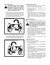
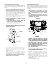
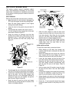
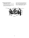
• From beneath the middle of the tractor, insert a
1/2 inch ratchet into the square hole of the deck
idler bracket. Refer to Figure 27.
• Using the ratchet for leverage, pivot the idler
bracket and movable idler pulley away from the
backside of the ‘V" belt; then lift the belt off of
both the movable and fixed idler pulleys. See
Figure 27.
Figure 27
• From beneath the rear of the tractor, slide the belt
off of the PTO pulley on the bottom of the engine.
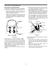
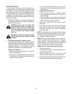
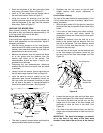
• Locate the LH and RH deck support pins on each
side of the deck. Pull the deck support pins
outward and lock in the disengaged position to
release the deck from the tractor’s LH and RH
deck lift arms. Refer to Figure 28.
• Raise the deck lift arms out of the rear hanger
bracket slots by raising the deck lift handle on the
tractor to its highest position.
Figure 28
• Slide the deck forward so that the deck front
hanger rod can be lifted out of the two slots of the
front deck bracket. After lifting the front hanger
rod out of the slots, slide the deck rearward so
that the rod can no longer engage the slots.
• Using care to prevent the front hanger rod from
falling back into the deck slots, gently slide the
cutting deck (from the right side) out from
underneath the tractor.
DECK INSTALLATION
To install the mower deck, proceed as follows:
• While holding up the deck front hanger rod,
carefully slide the deck underneath the right side
of the tractor.
• While still holding the front hanger rod, slide the
deck forward until the front hanger rod can be
lowered into the slots at the front of the deck.
• Lower the front hanger rod into the slots of the
front deck bracket, then slide the deck rearward.
• Maneuver the deck so that the slots in the two
rear deck hanger brackets approximately align
with the deck lift arms of the tractor. Refer to
Figure 28.
• Use the tractor deck lift handle to lower the deck
lift arms into the slots of the rear deck hanger
brackets.
• Pull the deck support pins outward and maneuver
the deck as necessary to align the holes in the
deck lift arm with the pins. Refer to Figure 28.
• When aligned, push each pin fully inward through
the lift arms to secure the arms in the rear hanger
bracket slots.
• Route the ‘V’ belt rearward beneath the tractor
frame and install the belt in the pulley of the PTO
clutch.
Fixed Idler
Pulley
Movable Idler
Pulley
Square
Hole
‘V’ Belt
Idler Bracket
Deck
Deck Lift Arm
Support
Pin
Rear Deck
Hanger Bracket
Rear Hanger
Bracket Slot